Retrotechtacular: The Tyranny Of Large Numbers

Although much diminished now, the public switched telephone network was one of the largest machines ever constructed. To make good on its promise of instant communication across town or around the world, the network had to reach into every home and business, snake along poles to thousands of central offices, and hum through the ether on microwave links. In its heyday it was almost unfathomably complex, with calls potentially passing through thousands of electronic components, any of which failing could present anything from a minor annoyance to a matter of life or death.

The brief but very interesting film below deals with “The Tyranny of Large Numbers.” Produced sometime in the 1960s by Western Electric, the manufacturing arm of the Bell System, it takes a detailed look at the problems caused by scaling up systems. As an example, it focuses on the humble carbon film resistor, a component used by the millions in various pieces of telco gear. Getting the manufacturing of these simple but critical components right apparently took a lot of effort. Initially made by hand, a tedious and error-prone process briefly covered in the film, Western Electric looked for ways to scale up production significantly while simultaneously increasing quality.

While the equipment used by the Western engineers to automate the production of resistors, especially the Librascope LGP-30 computer that’s running the show, may look quaint, there’s a lot about the process that’s still used to this day. Vibratory bowl feeders for the ceramic cores, carbon deposition by hot methane, and an early version of a SCARA arm to sputter gold terminals on the core could all be used to produce precision resistors today. Even cutting the helical groove to trim the resistance is similar, although today it’s done with a laser instead of a grinding wheel. There are differences, of course; we doubt current resistor manufacturers look for leaks in the outer coating by submerging them in water and watching for bubbles, but that’s how they did it in the 60s.

The productivity results were impressive. Just replacing the silver paint used for terminal cups with sputtered gold terminals cut 16 hours of curing time out of the process. The overall throughput increased to 1,200 pieces per hour, an impressive number for such high-reliability precision components, some of which we’d wager were still in service well into the early 2000s. Most of them are likely long gone, but the shadows cast by these automated manufacturing processes stretch into our time, and probably far beyond.

Continue reading “Retrotechtacular: The Tyranny Of Large Numbers”

Build Yourself A Useful Resistor Decade Box

If you’ve ever worked with guitar pedals or analog audio gear, you’ve probably realized the value of a resistor decade box. They substitute for a resistor in a circuit and let you quickly flick through a few different values at the twist of a knob. You can still buy them if you know where to look, but [M Caldeira] decided to build his own.

At its core, the decade box relies on a number of 11-position rotary switches. Seven are used in this case—covering each “decade” of resistances, from 1 ohm to 10 ohm and all the way up to 1 megaohm. The 11 positions on each switch allows the selection of a given resistance. For example, position 7 on the 100 ohm switch selects 700 ohms, and adds it to the total resistance of the box.

[M Caldeira] did a good job of building the basic circuit, as well as assembling it in an attractive, easy-to-use way. It should serve him well on his future audio projects and many others besides. It’s a simple thing, but sometimes there’s nothing more satisfying than building your own tools.

We’ve seen other neat designs like this in the past, including an SMD version and this neat digital decade box. Video after the break.

Continue reading “Build Yourself A Useful Resistor Decade Box”

Resistor Swap Gives Honda Insights More Power

A common complaint around modern passenger vehicles is that they are over-reliant on electronics, from overly complex infotainment systems to engines that can’t be fixed on one’s own due to the proprietary computer control systems. But even still, when following the circuits to their ends you’ll still ultimately find a physical piece of hardware. A group of Honda Insight owners are taking advantage of this fact to trick the computers in their cars into higher performance with little more than a handful of resistors.

The relatively simple modification to the first-generation Insight involves a shunt resistor, which lets the computer sense the amount of current being drawn from the hybrid battery and delivered to the electric motor. By changing the resistance of this passive component, the computer thinks that the motor is drawing less current and allows more power to be delivered to the drivetrain than originally intended. With the shunt resistor modified, which can be done with either a bypass resistor or a custom circuit board, the only other change is to upgrade the 100 A fuse near the battery for a larger size.

With these two modifications in place, the electric motor gets an additional 40% power boost, which is around five horsepower. But for an electric motor which can output full torque at zero RPM, this is a significant boost especially for a relatively lightweight car that’s often considered under-powered. It’s a relatively easy, inexpensive modification though which means the boost is a good value, although since these older hybrids are getting along in years the next upgrade might be a new traction battery like we’ve seen in the older Priuses.

Thanks to [Aut0l0g1c] for the tip!

Talking Ohmmeter Also Spits Out Color Bands For You

If you’ve got a resistor and you can’t read the color bands (or they’re not present), you can always just grab a multimeter and figure out its value that way. [Giacomo Yong Cuomo] and [Sophia Lin] have built an altogether different kind of ohmmeter, that can actually spit out color values for you, and even read the resistance aloud. It’s all a part of their final project for their ECE 4760 class.

The build is based around a Raspberry Pi Pico. It determines the value of a resistor by placing it in a resistor divider, with the other reference resistor having a value of 10 kΩ. The resistor under test is connected between the reference resistor and ground, while the other leg of the reference resistor is connected to 3.3 V. The node between the two resistors is connected to the Pi Pico’s analog-to-digital converter pin. This allows the Pico to determine the voltage at this point, and thus calculate the test resistor’s value based on the reference resistor’s value and the voltages involved.

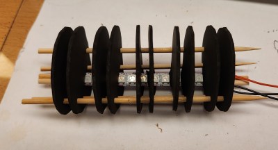
A large fake resistor provides user feedback. It’s filled with addressable LEDs, which light up the appropriate color bands depending on the test resistor’s value. It’s capable of displaying both 3-band, 4-band, and 5-band color configurations. While six-band resistors do exist, the extra band is typically used for denoting temperature coefficients which can’t readily be determined by this simple test. It can also play audio files to announce the resistance value over a speaker.

It’s a neat project that surely taught the duo many useful skills for working with microcontrollers. Plus, it’s kinda fun — we love the big glowing resistor. We’ve featured some other fancy resistors before, too!

Continue reading “Talking Ohmmeter Also Spits Out Color Bands For You”

Burnt Resistor Sleuthing

You smell smoke and the piece of gear you are working on stops working, probably at an inopportune time. You open it up and immediately see the burned remains of a resistor. You don’t have the schematic, the Internet has nothing to say, and the markings on the resistor are burned away. What do you do? [Learn Electronics Repair] has some advice.

The resistor is probably open, but even if it isn’t, you can’t count on any measurement you make. The burning could easily change the value. The technique comes from comments on one of his earlier videos where he had such a burned resistor but was able to find the correct value. He decided to test the suggestion: cut away the burned resistor and measure the pieces that are left. It probably won’t give you the exact value, but it will get you in the ballpark.

So a rotary tool did the surgery, and you can see it all in the video below. We aren’t sure this method would work on every type of resistor you might encounter, and surface mount will also present special problems. However, if you are stabbing in the dark anyway, it won’t hurt to try.

Everyone knows the smoke that comes out is magic. Sometimes, you cut into components by necessity. Other times, it is for art’s sake.

Continue reading “Burnt Resistor Sleuthing”

Hackaday Prize 2023: Over-the-Top Programmable Resistor Looks The Part And Performs

Every once in a while we get wind of a project that we’re reluctant to write up for the simple reason that it looks too good to be true. Not that projects need to be messy to be authentic, mind you, but there are some that are just so finished and professional looking that it gives us a bit of pause. [Sebastian]’s programmable precision resistor is a shining example of such a project

While [Sebastian] describes this as “a glorified decade resistance box,” and technically that’s exactly right — at its heart it’s just a bunch of precision resistors being switched into networks to achieve a specific overall resistance — there’s a lot more going on here than just that. The project write-up, which has been rolling out slowly over the last month or so, has a lot of detail on different topologies that could have been used — [Sebastian] settled on a switched series network that only requires six relays per decade while also minimizing the contribution of relay contact resistance to the network. Speaking of which, there’s a detailed discussion on that subject, plus temperature compensation, power ratings, and how the various decades are linked together.

For as much that’s interesting about what’s under the hood, we’d be remiss to not spend a little time praising the exterior of this instrument. [Sebastian] appears to have spared no expense to make this look like a commercial product, from the rack-mount enclosure to the HP-esque front panel. The UI is all discrete pushbuttons and knobs with a long string of 16-segment LEDs — no fancy touch-screens here. The panel layout isn’t overly busy, and looks like it would be easy to use with some practice. We’d love to hear how the front and rear panel overlays were designed, too; maybe in a future project update.

This honestly looks like an instrument that you’d pay a princely sum to Keithley or H-P to own, at least back in the late 1990s or so. Kudos to [Sebastian] for the attention to detail here.

"The Great Resistor" color code illumination project

The Great Resistor Embiggens The Smallest Value

With surface-mount components quickly becoming the norm, even for homebrew hardware, the resistor color-code can sometimes feel a bit old-hat. However, anybody who has ever tried to identify a random through-hole resistor from a pile of assorted values will know that it’s still a handy skill to have up your sleeve. With this in mind, [j] decided to super-size the color-code with “The Great Resistor”.

Resistor color code from Wikipedia with white background
How the resistor color-code bands work

At the heart of the project is an Arduino Nano clone and a potential divider that measures the resistance of the test resistor against a known fixed value. Using the 16-bit ADC, the range of measurable values is theoretically 0 Ω to 15 MΩ, but there are some remaining issues with electrical noise that currently limit the practical range to between 100 Ω and 2 MΩ.

[j] is measuring the supply voltage to help counteract the noise, but intends to move to an oversampling/averaging method to improve the results in the next iteration.

The measured value is shown on the OLED display at the front, and in resistor color-code on an enormous symbolic resistor lit by WS2812 RGB LEDs behind.

Inside view of the great resistor showing WS2812 LEDs and baffle plates
Inside The Great Resistor, the LEDs and baffle plates make the magic work

Precision aside, the project looks very impressive and we like the way the giant resistor has been constructed. It would look great at a science show or a demonstration. We’re sure that the noise issues can be ironed out, and we’d encourage any readers with experience in this area to offer [j] some tips in the comments below. There’s a video after the break of The Great Resistor being put through its paces!

If you want to know more about the history of the resistor color code bands, then we have you covered.  Alternatively, how about reading the color code directly with computer vision?

Continue reading “The Great Resistor Embiggens The Smallest Value”