[nextpage title=”Introduction”]
Today all motherboards have an embedded sound card (this feature goes by several different names, like on-board audio, on-board sound, integrated audio or integrated sound). In this tutorial we will explain how the on-board audio is produced, allowing you to understand what a codec is and what its importance to the audio quality is.
Some very high-end motherboards don’t come with the audio section on the motherboard, but in add-on card that comes with the product, being installed on a PCI Express x1 slot or on a special connector on the motherboard. This option is used only because some high-end motherboards have already so many connectors on the rear panel of the motherboard that the audio connectors don’t fit there, and using an add-on card solves this problem, as the connectors will now be available at one of the slots of the computer case.
[amazon box=”B00EO6X4XG” template=”table”]
Audio can be available in two different formats: analog or digital. Computers are digital systems so they can only produce and manipulate audio in digital format. The problem, however, is that in the real world audio is an analog entity. Speakers are expecting an analog signal so they can reproduce sounds; you can’t feed speakers with a digital signal – the so called “digital speakers” are in fact analog speakers with a digital-to-analog (DAC) converter converting the digital signal sent by the computer into analog signal.
On motherboards there is a chip called codec (short for coder/decoder) that is in charge of converting digital audio signals into analog and vice-versa. This component is very important as it defines the audio quality of a sound card, and we will talk a lot more about it later.
The process of converting the digital signal sent by the computer into an analog signal, so you can hear sound on your speakers – for example, when you play an MP3 file or when you play a video file – is called digital-to-analog conversion or DAC for short. The inverse process, i.e., converting analog sounds sent to the computer through a microphone or through its “line in” input into digital – for example, when you hookup a tape deck or a turntable to your PC to convert old music into MP3 files – is called analog-to-digital conversion or ADC for short.
On any sound card – including those embedded on motherboards – you can find two types of connectors: analog and digital. Analog connectors (usually 3.5 mm mini jacks) allow you to connect your sound card directly to speakers (i.e., “analog speakers”). This is the cheapest and easiest way to connect speakers to your PC.
Digital connection, also known as SPDIF (Sony/Phillips Digital Interconnect Format) can be found in two flavors, coaxial (using a mono RCA connector) or optical (using a connector called Toslink).
This connection allows you to connect your sound card to home theater receivers and digital speakers. As we have already explained, loudspeakers are analog devices. Home theater receivers and digital speakers have a digital-to-analog converter inside that converts the digital signal received into analog and then send the signal to the speakers.
Digital connection provides some advantages compared to analog connection. First, usually home theater receivers and digital speakers use a better codec than the one used on the motherboard and because of that the audio quality is higher (lower noise level, mainly).
Secondly, home theater receivers and digital speakers may provide features not found on analog speakers, like Dolby Pro Logic, which simulates surround sound when the original sound source is just stereo (i.e., two channels only) – using analog speakers you can only have this kind of feature if the software you are using provide them.
And in third place, with digital connection you need just one cable to connect your PC to your home theater or digital speakers, while with analog connection you need one cable for each pair of speakers (on a 5.1 system you will need three cables, for example).
The drawback of digital connection is price, as the components involved with digital connection are more expensive (the cost of a home theater receiver and a set of speakers is far higher than the cost of a set of analog speakers for your PC), the reason being the use of a more expensive codec and also the cost of the decoders for several additional enhancements, like the abovementioned Dolby Pro Logic.
In Figure 1, you can see the connectors found on the rear panel of a motherboard (ASUS P5K-E) showing you the digital (Figure 2) and analog (Figure 3) audio connectors.
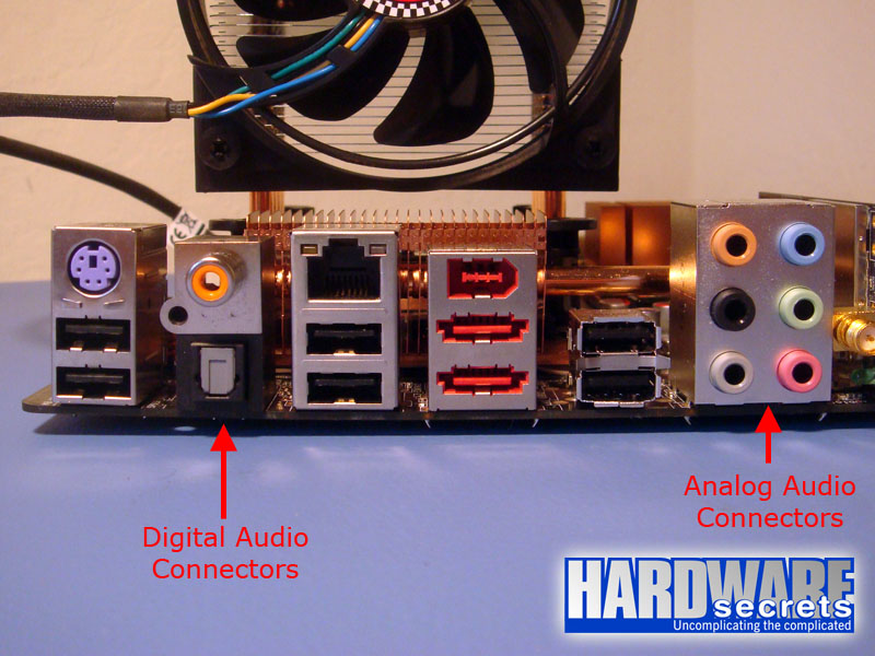
Figure 1: Connectors found on the rear panel of a motherboard (ASUS P5K-E).

Figure 2: Digital audio connectors (coaxial on the top, optical on the bottom).

Figure 3: Analog audio connectors.
The number of analog connectors you will find on your motherboard will depend on how many audio channels your motherboard has (2, 4, 6 or 8) – by the way, “channels” means “outputs for individual speakers,” and 5.1 and 6 are synonyms, as 7.1 and 8 are also synonyms; these are different ways of saying the same thing. On the best case (eight channels – a.k.a. 7.1 format) you will have six connectors like portrayed in Figure 3. The color code used by analog audio jacks is the following:
- Pink: Mic in
- Blue: Line in
- Green: Front speakers out
- Black (or dark blue on some older boards): Rear speakers out
- Orange: Center/subwoofer out
- Gray: Middle speakers out
On motherboards with just two audio channels you will find only the pink, blue and green jacks. On some motherboards with four or six channels you won’t find the black and orange jacks. In this case the blue jack is used for both line in and rear speakers out, and the pink jack is used for both mic in and center/subwoofer speakers out.
Of course this configuration isn’t the ideal, as whenever you want to use any of these jacks for another function (for instance, connect a microphone to talk on Skype) you will have to manually remove one plug (the speaker plug) and install another plug (the microphone plug) and switching them again later (after you finished using Skype).
Also some motherboards with eight audio channels do not provide the gray connector, allowing only 5.1 analog speakers to be connected directly to the motherboard. In this case if you want to use all the eight channels you will need to connect your motherboard to a 7.1 home theater receiver or digital speakers using the SPDIF (i.e., digital) connection.
[nextpage title=”The South Bridge Chip”]
Technically speaking there are two ways of integrating audio on the motherboard. The most common one is using the system CPU to process audio, under a technique called HSP (Host Signal Processing), with the south bridge chip from the chipset providing the necessary interfacing circuit with the external world.
The second way – which nowadays is only seen on few very high-end motherboards – is using a dedicated controller to control and process the audio and thus not using the system CPU for these tasks.
But both the south bridge chip and dedicated controllers aren’t capable of dealing with analog audio, only with digital audio, requiring an external chip – the codec – to perform the interface between the chip and the analog connectors.
The south bridge chip – also called ICH or I/O Controller Hub by Intel –controls the majority of peripheral ports located on the motherboard, like the USB ports and the x1 PCI Express connections. It is a big chip and usually it is located far away from the CPU on the motherboard, normally with a passive heatsink on top. The big chip near the CPU is the north bridge chip.
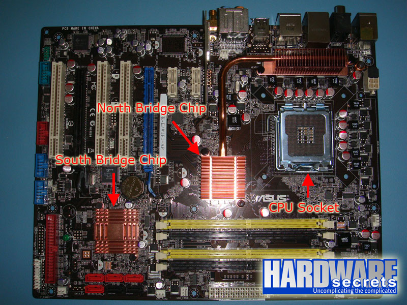
Figure 4: Location of the south bridge chip on a motherboard.
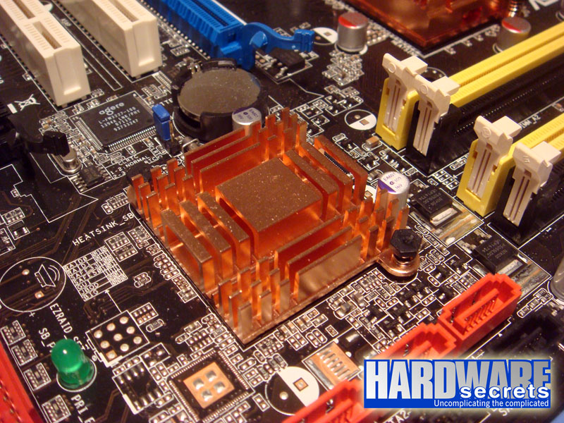
Figure 5: South bridge chip with its passive heatsink.
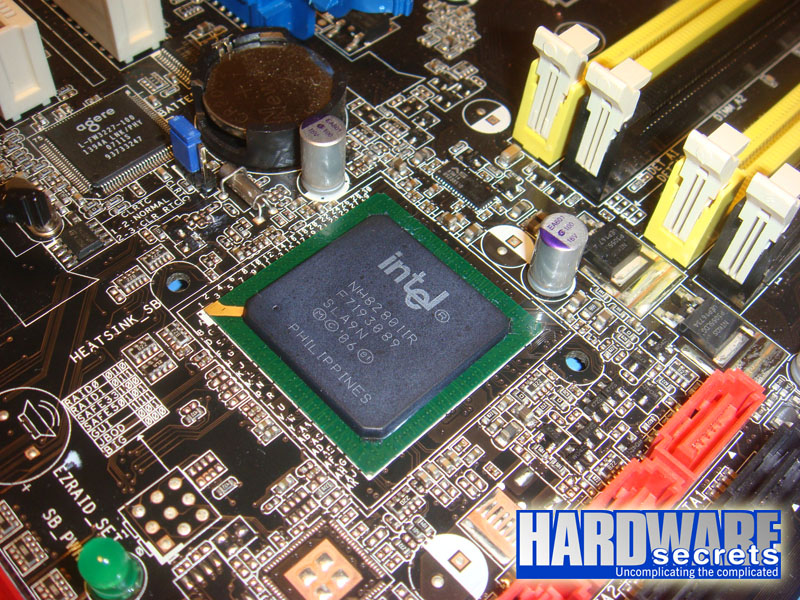
Figure 6: South bridge chip with its passive heatsink removed.
In Figure 7, you can see part of the block diagram of a south bridge chip. Since this block diagram was too big, we are only showing the part that is of interest for our explanations: the audio interface (“Intel High Definition Audio” in Figure 7). This block diagram is from an Intel ICH9 south bridge chip, used by several mainstream chipsets like P965 and P35 (and portrayed on the pictures above).

Figure 7: Block diagram of a south bridge chip.
As you can see the audio interface is very simple, providing only a few pins, which are connected to the audio codec located on the motherboard.
[nextpage title=”The Audio Codec”]
The south bridge chip or the audio controller can’t deal with analog audio. They need a small chip called audio codec (short for coder/decoder) to make the proper digital-to-analog (DAC) and analog-to-digital conversions (ADC).
Digital-to-analog conversion is made when the computer is sending sounds to the speakers, while analog-to-digital conversion is made when you are feeding the computer with an external analog audio source (for example, when you connect a tape deck or a turntable to the PC to convert music into MP3 or CD).
Physically speaking the audio codec is a very small chip measuring ¼ sq. in. (7 mm2) and usually located on the rear border of the motherboard (see Figure 8). The two most popular manufacturers of this chip is Realtek (RTC), whose chips are named starting with the letters ALC, and Analog Devices (ADI, also known as “SoundMax”), whose chips are named starting with the letters AD. On Figures 9 and 10 we show you examples of codecs from these two manufacturers.

Figure 8: Location of the audio codec on a motherboard.

Figure 9: Realtek ALC888S codec.
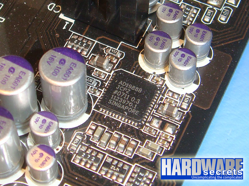
Figure 10: Analog Devices AD1988B codec.
In Figure 11 we show you a small diagram explaining the relationship of the south bridge chip, the codec and the audio connectors found on the motherboard.

Figure 11: How the on-board audio works.
[nextpage title=”Audio Quality”]Since the codec is in charge of the digital-to-analog and analog-to-digital conversions, the quality of analog audio depends exclusively on the quality of the codec used on the motherboard. There are several parameters that can be used to judge the quality of an audio codec.
Below we listed the main parameters that you should use to compare codecs (and thus the quality of the on-board audio of a motherboard) and the most common values for each parameter. The higher the number, the better.
- Channels: 2, 4, 6 (5.1), 8 (7.1) or 10 (8+2).
- Resolution: 16-, 18-, 20- or 24-bit.
- Sampling rate: 44.1, 48, 96 or 192 kHz.
- Signal-to-noise ratio (SNR): 80 to over 100 dB.
It is important to note that several codecs offer one value for its inputs and another value for its outputs – for example, offering up to 192 kHz sampling rate for its outputs but only up to 96 kHz to its inputs (which is the case of Realtek ALC888S codec portrayed in Figure 8, by the way).
This happens because while all users use the motherboard audio output and can judge audio quality by listening to audio produced by his or her PC, only a few use the “line in” input offered by the motherboard (several users use the “mic in” input for applications like Skype but since this input is used only for human voice, the quality doesn’t need to be the best).
Based on this fact codec manufacturers provide cheaper codecs with lower specs for their inputs, which are chosen by motherboard manufacturers in order to cut costs. In fact you will only find codecs with high quality for their inputs on a few very high-end (and very expensive) motherboards.
By the way, on the codec datasheet or specs page on the manufacturer website the outputs are usually referred as “DAC” and the inputs are usually referred as “ADC.” This will help you to find out the specs of a given codec.
Now let’s explain in details each item from our list above.
Channels are the number of independent outputs a codec offers. In the past sound cards were only able to provide two channels – left and right, i.e., standard stereo sound. Then came the basic surround sound with four channels, with two speakers (left and right) on the front and two speakers (left and right) on the rear. Nowadays these two options are only found on very old motherboards or on very low-end ones.
The minimum number of channels you will find today is six, also known as 5.1. This is the same audio standard used by DVDs. Here we have two front speakers, two rear speakers, one center speaker (mainly used for voice; for example, on news broadcast or on a movie when the characters are talking the sound will come from this speaker) and one subwoofer channel – also known as LFE (Low Frequency Effects) –, which is in charge of creating a more realistic experience by reinforcing low frequency (bass) sounds.
Eight-channel audio, also known as 7.1, provides the same specs of 5.1 audio, but adding two more speakers between the front speaker and the rear speaker, one at each side (left and right). These speakers are also known as middle speakers. This is the same standard used by high-def discs, i.e., HD-DVD and Blu-Ray.
And finally the latest addition is the 10-channel audio, which is a misnomer, as it doesn’t add two more channels to the surround system but provides two independent channels (left and right) for headphones. This system is better described as 8+2.
On all other systems the headphone jack located on the frontal panel of the case is connected in parallel with the line out (front speakers) output and thus provides the exact same sound that is being sent to the front speakers. On the 8+2 system the frontal headphone jack is independent from the front speakers output and programs can send a different audio signal to the headphones while playing another sound on the frontal speakers.
Think of games that use VoIP technology like Battlefield, where users can talk to each other through a headphone/microphone set, and you will quickly see the benefits of this system: users won’t listen on the headphone the sounds of the game like explosions and gunshots, only their conversation with other users, while keeping the game sounds playing at the same time on all speakers.
Resolution and sampling rate are two parameters that would take us a long time to explain exactly what they are. We have already written a tutorial called How Analog-to-Digital Converter (ADC) Works where we explained them in details. If you don’t want to read this tutorial all you need to know is that the higher these numbers, the better the audio quality is.
And finally we have signal-to-noise ratio, also called SNR, which measures the noise level produced by the codec. In our opinion this is one parameter that average users don’t pay a lot of attention, but they should.
Keep in mind that what we are talking here is the noise produced by the codec, not the noise that is already embedded on the audio source. This parameter has nothing to do with the noise that is already inside a video file or a MP3 file that you may have.
To understand what we are talking about, make a simple experience. At home, find a sound system that still has a tape deck. Put a tape to play, press the pause key and increase the volume. You will hear a lot of noise (technically called white noise) that is being produced by the tape deck and isn’t inside the tape you are playing (as the tape is stopped). That is the noise we are talking about. Of course you don’t want a motherboard that inserts noise on your sound.
The signal-to-noise ratio is measured on a unit called decibel (dB). The higher this number, the better. Ideally you should have a motherboard with a codec that has a signal-to-noise ratio of at least 100 dB for the best audio quality possible. Mainstream codecs offer a signal-to-noise ratio of 95 dB or 97 dB, which is “almost there” and will provide a very good audio quality for Average Joe.
The problem, however, is the signal-to-noise ratio for the audio inputs. The signal-to-noise ratio advertised by the motherboard or codec manufacturer is for the codec analog outputs only (DAC SNR). Like we explained, motherboard manufacturers will usually pick a codec with input specs lower than output specs.
If you plan to professionally work capturing and editing analog audio – converting VHS tapes to DVD, converting tapes and LP’s into MP3 or CD and similar tasks – then you should buy a motherboard (or an add-on sound card) that uses a codec providing at least 95 dB SNR. Below that you will hear noise on your work, which is bad as it will give you a bad name with your customers.
Unfortunately mainstream codecs will provide an input SNR of 90 dB or even 85 dB, which is really bad. Of course you only need to worry about this if you are going to work capturing and editing analog audio. If this isn’t your case – like it isn’t for almost all users – you should not worry about this.
Now that you know the basic specs of a codec you will be able to compare the audio quality of different codecs (and thus motherboards) available on the market. To make things easier, we compiled a series of tables listing the basic specs of the most popular audio codecs found on the market.

Leave a Reply