Abstract
Cooperative dynamic manipulation enlarges the manipulation repertoire of human–robot teams. By means of synchronized swinging motion, a human and a robot can continuously inject energy into a bulky and flexible object in order to place it onto an elevated location and outside the partners’ workspace. Here, we design leader and follower controllers based on the fundamental dynamics of simple pendulums and show that these controllers can regulate the swing energy contained in unknown objects. We consider a complex pendulum-like object controlled via acceleration, and an “arm—flexible object—arm” system controlled via shoulder torque. The derived fundamental dynamics of the desired closed-loop simple pendulum behavior are similar for both systems. We limit the information available to the robotic agent about the state of the object and the partner’s intention to the forces measured at its interaction point. In contrast to a leader, a follower does not know the desired energy level and imitates the leader’s energy flow to actively contribute to the task. Experiments with a robotic manipulator and real objects show the efficacy of our approach for human–robot dynamic cooperative object manipulation.
Electronic supplementary material
The online version of this article (doi:10.1007/s12369-017-0415-x) contains supplementary material, which is available to authorized users.
Keywords: Physical human–robot interaction, Cooperative manipulators, Adaptive control, Dynamics, Haptics, Intention estimation
Introduction
Continuous energy injection during synchronized swinging motion enables a human and a robot to lift a bulky flexible object together onto an elevated location. This example scenario is illustrated in Fig. 1a and combines the advantages of cooperative and dynamic manipulation. Cooperative manipulation allows for the manipulation of heavier and bulkier objects than one agent could manipulate on its own. A commonly addressed physical human–robot collaboration scenario is, e.g., cooperative transport of rigid bulky objects [44]. Such object transport tasks are performed by kinematic manipulation, i.e., the rigid object is rigidly grasped by the manipulators [32]. In contrast, dynamic object manipulation makes use of the object dynamics, with the advantage of an increased manipulation repertoire: simpler end effectors can handle a greater variety of objects faster and outside the workspace of the manipulator. Dynamic manipulation examples are juggling, throwing, catching [29] as well as the manipulation of underactuated mechanisms [8], such as the flexible and the pendulum-like objects in Fig. 1a, b.
Fig. 1.

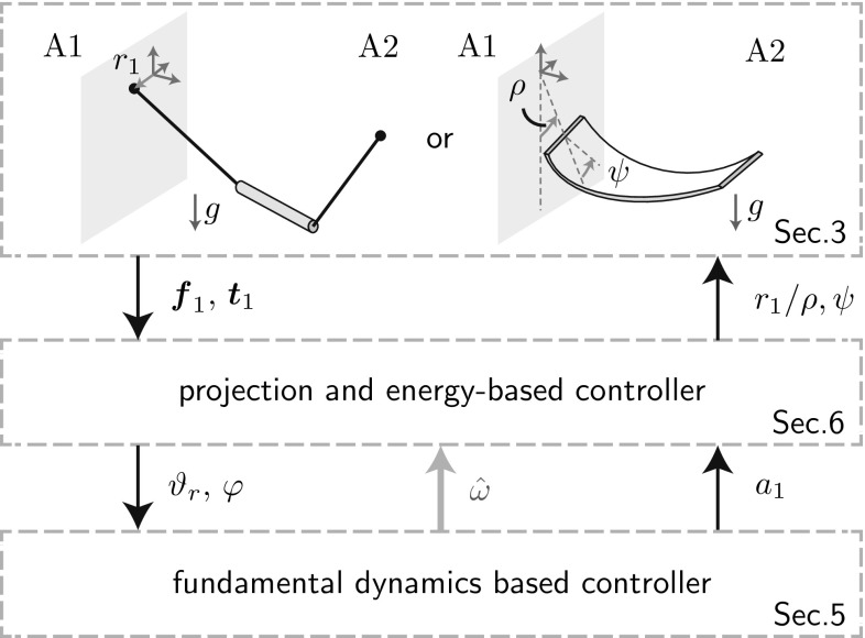
Approach overview: (1) Interpretation of flexible object swinging as a combination of pendulum swinging and rigid object swinging. (2) Approximation of pendulum swinging by the t-pendulum with 1D acceleration inputs and of flexible object swinging by the afa-system with 1D torque inputs. (3) Projection of the t-pendulum and the afa-system onto the abstract cart-pendulum and abstract torque-pendulum, respectively. (4) Extraction of the closed-loop fundamental dynamics. (5) Fundamental dynamics-based natural frequency estimation and leader and follower controller design
In this article, we take a first step towards combining the advantages of cooperative and dynamic object manipulation by investigating cooperative swinging of underactuated objects. The swinging motion naturally synchronizes the motion of the cooperating agents. Energy can be injected in a favorable arm configuration for a human interaction partner (stretched arm) and task effort can be shared among the agents. Moreover, the accessible workspace of the human arm and robotic manipulator is increased by the swinging motion of the object and by a possible subsequent throwing phase. In order to approach the complex task of cooperative flexible object swinging in Fig. 1a, we split it up into its two extremes, which are swinging of pendulum-like objects which oscillate themselves (b) and swinging of rigid objects, where the agents’ arms together with the rigid object form an oscillating entity (c). In our initial work, we treated pendulum-like object swinging [13] based on the assumption that all system parameters are known. This assumption was alleviated in [14] by an adaptive approach.
The contribution of this work is three-fold: firstly, we experimentally verify the adaptive approach presented in [14]. Secondly, we combine our results from cooperative swinging of pendulum-like objects and human–human swinging of rigid objects in [15], towards cooperative swinging of flexible objects. Our third contribution lies in the unified presentation of modeling the desired oscillation of pendulum-like and flexible objects through simple pendulum abstractions of equal fundamental dynamics (see two paths in Fig. 1). In the following, we discuss the state of the art related to different aspects of our proposed control approach.
Dynamic Manipulation in Physical Human–Robot Interaction
Consideration and exploitation of the mutual influence is of great importance when designing controllers for natural human–robot interaction [45]; even more when the agents are in physical contact. Only little work exists on cooperative dynamic object manipulation in general, and in the context of human–robot interaction in particular. In [25] and [30], a human and a robot perform rope turning. For both cases, a stable rope turning motion had to be established by the human before the robot was able to contribute to sustaining it. The human–robot cooperative sawing task considered in [38] requires adaptation on motion as well as on stiffness level in order to cope with the challenging saw-environment interaction dynamics.
In contrast, cooperative kinematic manipulation of a common object by a human and a robot has seen great interest. Kosuge et al. [26] designed first rather passive gravity compensators, which have been developed further to robotic partners who actively contribute to the task, e.g., [33]. Active contribution comes with own plans and thus own intentions, which have to be communicated and negotiated. Whereas verbal communication allows humans to easily exchange information, human–human studies have shown that haptic coupling through an object serves as a powerful and fast haptic communication channel [21]. In this work, the robotic agent is limited to measurements of its own applied force and torque. Thus, the robot has to use the haptic communication channel to infer both, the intention of the partner and the state of the object.
Cooperation of several agents allows for role allocation. Human–human studies in [40] showed that humans tend to specialize during haptic interaction tasks and motivated the design of follower and leader behavior [17]. Mörtl et al. [34] assigned effort roles that specify how effort is shared in redundant task directions. Also, the swing-up task under consideration allows for effort sharing. In kinematic physical interaction tasks, the interaction forces are commonly used for intention recognition, e.g., counteracting forces are interpreted as disagreement [20, 34]. Furthermore, the leader’s intention is mostly reflected in a planned trajectory. For the swing-up task, on the contrary, the leader’s intention is reflected in a desired object energy, which is unknown to the follower agent. Dynamic motion as well as a reduced coupling of the agents through the flexible or even pendulum-like object prohibit a direct mapping from interaction force to intention. We propose a follower that monitors and imitates the energy flow to the object in order to actively contribute to the task.
Simple Pendulum Approximation for Modeling and Control
The pendulum-like object in Fig. 1b belongs to the group of suspended loads. Motivated by an extended workspace, mechanisms with single [8] and double [51] cable-suspensions were designed and controlled via parametric excitation to perform point to point motion and trajectory tracking. An impressive example of workspace extension is presented in [9], where a quadrotor injects energy into its suspended load such that it can pass through a narrow opening, which would be impossible with the load hanging down. The pendulum-like object in Fig. 1b is similar to the suspended loads of [50] and [51]. However, the former work focuses on oscillation damping and the latter uses one centralized controller.
In contrast to pendulum-like objects, rigid objects tightly couple the robot and the human motion. Thus, during human–robot cooperative swinging of rigid objects as illustrated in Fig. 1c, the robot needs to move “human-like” to allow for comfort on the human side. On this account, we conducted a pilot study on human–human rigid object swinging reported in [15]. The observed motion and frequency characteristics suggest that the human arm can be approximated as a torque-actuated simple pendulum with pivot point in front of the human shoulder. This result is in line with the conclusion drawn in [22] that the preferred frequency of a swinging lower human arm is dictated by the physical properties of the limb rather than the central nervous system.
Manipulation of flexible and deformable objects is a challenging research topic also at slow velocities. While the finite elements method aims at exact modeling [28], the pseudo-rigid object method offers an efficient tool to estimate deformation and natural frequency [49].
Here, instead of aiming for an accurate model, we achieve stable oscillations of unknown flexible objects by making use of the fact that the desired oscillation is simple pendulum-like. Simple pendulum approximations have been successfully used to model and control complex mechanisms, e.g., for brachiating [36] or dancing [46]. The swing-up and stabilization of simple pendulums in their unstable equilibrium point is commonly used as benchmark for linear and nonlinear control techniques [1, 18]. Instead of a full swing-up to the inverted pendulum configuration, our goal is to reach a periodic motion of desired energy content. Based on virtual holonomic constraints, [19] and achieve desired periodic motions. Above controllers rely on thorough system knowledge, whereas our final goal is the manipulation of unknown flexible objects.
Adaptive Control for Periodic Motions and Leader–Follower Behavior
The cooperative sawing task in [38] is achieved via learning of individual dynamic movement primitives for motion and stiffness control with a human tutor in the loop. Frequency and phase are extracted online by adaptive frequency oscillators [39]. The applicability of learning methods as learning from demonstration [4] or reinforcement learning [16] to nonlinear dynamics is frequently evaluated based on inverted pendulum tasks. Reinforcement learning often suffers from the need of long interactions with the real system and from a high number of tuning parameters [35, 37]. Only recently, Deisenroth et al. showed how Gaussian processes allow for faster autonomous reinforcement learning with few parameters in [10]. Neural networks constitute another effective tool to control nonlinear systems, which have also been applied to adaptive leader–follower consensus control in, e.g., [47].
In this work, we apply model knowledge of the swinging task to design adaptive leader/follower controllers for swinging of unknown flexible objects, without the need of a learning phase. Identification of the underlying fundamental dynamics allows us to design leader and follower controllers which only require few parameters of distinct physical meaning.
Overview of the Fundamental Dynamics-Based Approach
This section highlights the main ideas of the proposed approach and structures the article along Figs. 1 and 2. Individual variables will be introduced in subsequent sections and important variables are listed in Table 1.
Fig. 2.
Implementation overview block diagram. Based on measured force and torque , the complex afa-system and t-pendulum are projected onto their simple pendulum variants. From the extracted FD states and the natural frequency is estimated and leader or follower behavior is realized . Energy-based controllers convert the amplitude factor into desired end effector motion defined by or and
Table 1.
Important variables and abbreviations
| FD | Fundamental dynamics |
|---|---|
| / | Force/torque applied by agent i |
| Position, velocity, acceleration of agent i in x-direction with respect to its initial position | |
| Torque applied at shoulder of virtual arm | |
| / | Desired/undesired oscillation DoF |
| Virtual arm deflection angle | |
| Oscillation DoF of abstract simple pendulums | |
| Phase angle | |
| E, | Energy, energy of oscillation j |
| Amplitude of oscillation j (energy equivalent) | |
| Phase space radius (approx. energy equivalent) | |
| Amplitude factor of agent i | |
| Natural frequency | |
| / | Small angle/geometric mean approximation |
| Relative energy contribution of agent i | |
| Agent Ai | |
| , | Follower, leader agent |
| / | Parameters of object/virtual arm |
| Reference dynamics | |
| Projection of onto xy-plane | |
| / | Estimate/ desired value of |
In this work, we achieve cooperative energy injection into unknown flexible objects based on an understanding of the underlying desired fundamental dynamics (FD). Figure 1 illustrates the approximation steps taken that lead from human–robot flexible object swinging (a) to the FD (h). Pendulum-like objects (b) constitute the extreme end on the scale of flexible objects (a) with respect to the coupling strength between the agents. The especially weak coupling allows us to isolate the object from the agents’ end effectors and represent the agent’s influence by acceleration inputs. In the following, we refer to the isolated pendulum-like object (d) as t-pendulum due to its trapezoidal shape. In order to achieve our final goal of flexible object swinging, we consolidate our insights on pendulum and rigid object swinging (see step 2 in Fig. 1). We exploit the result that human arms behave as simple pendulums during rigid object swinging [15] and approximate the human arms by simple pendulums actuated via torque at the shoulder joints. We abbreviate the resultant “arm—flexible object—arm” system (e) as afa-system.
We do not try to extract accurate dynamical models, but make use of the fact that the desired oscillations are simple pendulum-like. The desired oscillations of the t-pendulum and the afa-system are then represented by cart-actuated (f) and torque-actuated (g) simple pendulums, respectively. We extract linear FD (h) which describes the phase and energy dynamics of the simple pendulum approximations controlled by a variant of the swing-up controller of Yoshida [48]. The FD allows for online frequency estimation (i), controlled energy injection and effort sharing among the agents (j).
The block diagram in Fig. 2 visualizes the implementation with input and output variables. The blocks will be detailed in the respective sections as indicated in Figs. 1 and 2. We would like to emphasize here that the proposed robot controllers generate desired end effector motion solely based on force and torque measurements at the robot’s interaction point.1
The remainder of the article is structured as follows. In Sect. 3 we give the problem formulation. This is followed by the FD derivations in Sect. 4, on which basis the adaptive leader and follower controllers are introduced and analyzed in Sect. 5. In Sect. 6, we apply the FD-based controllers to the two-agent t-pendulum and afa-system. We evaluate our controllers in simulation and experiments in Sects. 7 and 8, respectively. In Sect. 9, we discuss design choices, limitations and possible extensions of the presented control approach. Section 10 concludes the article.
Problem Formulation for Cooperative Object Swinging
In this section, we introduce relevant variables and parameters of the t-pendulum and afa-system of Fig. 1d, e. Thereafter, we formally state our problem. Note that we drop the explicit notation of time dependency of the system variables where clear from the context.
The t-Pendulum
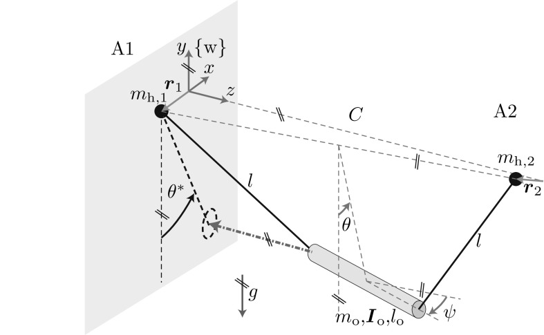
Figure 3 shows the t-pendulum. Without loss of generality, we assume that agent A1 R is the robot who cooperates with a human A2 H. The t-pendulum has 10 degrees of freedom (DoFs), if we assume point-mass handles: the 3D positions of the two handles and representing the interaction points of the two agents A1 and A2 and 4 oscillation DoFs. The oscillation DoF describes the desired oscillation and is defined as the angle between the y-axis and the line connecting the center between the two agents and the center of mass of the pendulum object. The oscillation DoF describes oscillations of the object around the y-axis and is the major undesired oscillation DoF. Experiments showed that oscillations around the object centerline and around the horizontal axis perpendicular to the connection line between the interaction partners2 play a minor role and are therefore neglected in the following.
Fig. 3.
The t-pendulum (adapted from [13]): cylindrical object of mass , length and moment of inertia under the influence of gravity g attached via massless ropes of length l to two handles of mass located at with . The location is defined with respect to the world fixed coordinate system . The location is defined with respect to the fixed point in , where C is the initial distance between the two agents. Pairs of parallel lines at the same angle indicate parallelity
The agents influence the t-pendulum by means of handle accelerations and . Although we assume cooperating agents, the only controllable quantity of agent is its own acceleration . The acceleration of agent acts as a disturbance as it cannot be directly influenced by agent . We limit the motion of agent to the x-direction for simplicity, which yields the one dimensional input . Experiments showed that 1D motion is sufficient and does not disturb a human interaction partner in comfortable 3D motion, because the pendulum-like object only loosely couples the two agents. The forces applied at the own handle are the only measurable quantity of agent A1, i.e. measurable output .
The afa-System
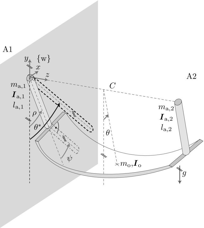
Figure 4 shows the afa-system. The cylindrical arms are actuated by shoulder torque around the z-axis and . For simplicity, we limit the arm of agent to rotations in the xy-plane. Note that we use the same approximations for the side of agent for ease of illustration, although a human interaction partner can move freely. The angle between the negative y-axis and the arm of agent is the oscillation DoF . The angle describes the wrist orientation with respect to the arm in the xy-plane (see right angle marking in Fig. 4). Thus, position and orientation of the interaction point of A1 are defined by the angles and . We regard excessive and unsynchronized -oscillations as undesired. The wrist joint is subject to damping and stiffness . The desired oscillation DoF is defined as the angle between the y-axis and the line connecting the center between the two agents and the center of mass of the undeformed flexible object (indicated by a cross in Fig. 4). The input to the afa-system from the perspective of agent is its shoulder torque . Agent receives force and torque signals at its wrist: measurable output .
Fig. 4.
The afa-system: two cylindrical arms connected at their wrist joints through a flexible object of mass and deformation dependent moment of inertia under the influence of gravity g. The two cylindrical arms are of mass , moment of inertia and length with and have their pivot point at the origin of the world fixed coordinate system and at in , respectively. Pairs of parallel lines at the same angle indicate parallelity
Problem Statement
Our goal is to excite the desired oscillation to reach a periodic orbit of desired energy level and zero undesired oscillation . The desired energy is then equivalent to a desired maximum deflection angle or a desired height , at which the object could potentially be released. We define the energy equivalent for a general oscillation :
Definition 1
The energy equivalent is a continuous quantity which is equal to the maximum deflection angle the -oscillation would reach at its turning points () in case
For the rest of the article, we interchangeably use , and , according to Definition 1 with to refer to the energies contained in the - and -oscillations, respectively.
We differentiate between leader and follower agents. For a leader the control law is a function of the measurable output and the desired energy . We formulate the control goal as follows
 |
1 |
Hence, the energy of the -oscillation should follow first-order reference dynamics within bounds . The reference dynamics are of inverse time constant and converge to the desired energy . Furthermore, the energy contained in the -oscillation should stay within after the settling time . We only consider desired energy levels of to avoid undesired phenomena as, e.g., slack suspension ropes in case of the pendulum-like object.
A follower does not know the desired energy level . We define a desired relative energy contribution for the follower based on the integrals over the energy flows of the leader and the follower
| 2 |
Our goal is to split the energy effort among the leader and the follower such that the follower has contributed the fraction within bounds at the settling time . To this end, we formulate the follower control goal as
| 3 |
The energy of the undesired oscillation should be kept within .
Fundamental Dynamics
In this section, we introduce the abstract cart-pendulum and abstract torque-pendulum as approximations for the desired system oscillations of the t-pendulum and the afa-system (see Fig. 1d–g). This is followed by an introduction of the energy-based controller. Finally, we present the fundamental dynamics (FD) of the cart-pendulum and abstract torque-pendulum, which result from a state transformation, insertion of the energy-based controller and subsequent approximations.
The Abstract Cart-Pendulum
For the ideal case of and agents that move along the x-direction in synchrony , the desired deflection angle is equal to the projected deflection angle (projection indicated by the dashed arrow in Fig. 3). This observation motivates us to approximate the desired system behavior of the pendulum-like object as a cart-pendulum with two-sided actuation (see Fig. 1f)
| 4 |
with reduced state consisting of deflection angle and angular velocity and the small angle approximation of the natural frequency . We use the variables for the deflection angle of the abstract simple pendulum variants in contrast to the actual deflection angle of the complex objects. On the desired periodic orbit we have . The small angle approximation of the natural frequency depends on gravity g and abstract pendulum parameters: mass , distance between pivot point and the center of mass and the resultant moment of inertia around the pendulum pivot point . The parameters and represent one side of the t-pendulum, i.e. half of the mass and moment of inertia of the pendulum mass. By dividing the input accelerations by 2 in (4), we consider the complete mass and moment of inertia of the t-pendulum. We call this pendulum abstract cart-pendulum, where cart refers to the actuation through horizontal acceleration. The term abstract emphasizes the simplification we make by approximating the agents’ influences as summed accelerations and neglecting .
The Abstract Torque-Pendulum
The afa-system simplifies to the two-link pendubot [43] with oscillation DoFs and , when being projected into the xy-plane of agent A1 (see gray dash-dotted link in Fig. 4). For , the pendubot further reduces to a single link pendulum actuated through shoulder torques of agents A1 and (see Fig. 1g)
| 5 |
We call this pendulum abstract torque-pendulum. As for the abstract cart-pendulum, the parameter represents the moment of inertia of one side of the afa-system. Similar to the t-pendulum, we define a projected deflection angle (see Fig. 4). On the desired periodic orbit we have .
Energy-Based Control for Simple Pendulums
Here, we recapitulate important simple pendulum fundamentals and introduce the energy-based controller to be applied to the abstract simple pendulums. For the following derivations, we assume zero handle velocity for the cart-pendulum , which is the case for the torque-pendulum by construction. The energy contained in both abstract pendulums is then
| 6 |
According to Definition 1, the energy equivalent is equal to the maximum deflection angle reached at the turning points for angular velocity
| 7 |
Setting (6) equal to (7), we can express in terms of the state
| 8 |
with . In contrast to the energy , which also depends on mass and moment of inertia of the object, the amplitude only depends on the small angle approximation of the natural frequency . Therefore, we will use as the preferred energy measure in the following.
Simple pendulums constitute nonlinear systems with an energy dependent natural frequency . No analytic solution exists for , but it can be obtained numerically by with the arithmetic-geometric mean [6]. Already the first iteration of yields good estimates for
| 9 |
with relative error 0.748 % for the arithmetic mean approximation and 0.746 % for the geometric mean approximation at with respect to the sixth iteration of . In the following, we make use of the geometric mean approximation within derivations and as ground truth for comparison to the estimate in simulations and experiments.
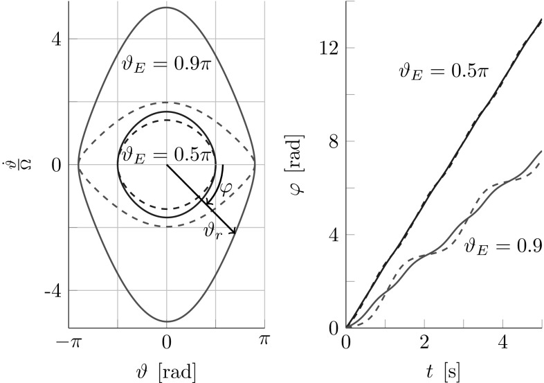
The pendulum nonlinearities are visualized in phase portraits on the left side of Fig. 5 for two constant energy levels and . The inscribed phase angle is
| 10 |
with normalization factor . The right side of Fig. 5 displays the phase angle over time. The normalization factor is used to partly compensate for the pendulum nonlinearities, with the result of an almost circular phase portrait and an approximately linearly rising phase angle
| 11 |
Figure 5 shows that normalization with the more accurate geometric mean approximation of the natural frequency allows for a better compensation of the pendulum nonlinearities than a normalization with the small angle approximation .
Fig. 5.
Phase portrait (left) and phase angle over time (right) at constant energy levels (blue) and (red) of a lossless simple pendulum. Normalization with marked via solid lines and via dashed lines. For energies up to and a normalization with , the phase space is approximately a circle with radius and the phase angle rises approximately linear over time. Figure adapted from [14]
The main idea of the energy control for the abstract cart-pendulum is captured in the control law [48]
| 12 |
where the amplitude factor regulates the sign and amount of energy flow contributed by agent Ai to the abstract cart-pendulum, with . A well-timed energy injection is achieved through multiplication with , which according to (11) excites the pendulum at its natural frequency. For the abstract torque-pendulum we choose a similar control law with
| 13 |
Cartesian to Polar State Transformation
The abstract cart- and torque-pendulum dynamics in (4) and (5) are nonlinear with respect to the states . The index indicates that the angle and angular velocity represent the cartesian coordinates in the phase space (see left side of Fig. 5). We expect the system energy to ideally be independent of the phase angle , which motivates a state transformation to and for simple adaptive control design. Solving (10) for and insertion into (8) yields
| 14 |
However, there is no analytic solution for from (14). Therefore, we approximate the system energy through the phase space radius
| 15 |
From Fig. 5 we see that the phase space radius is equal to the energy at the turning points (). For energies and a normalization with , the phase space is almost circular and thus also for .
The phase angle and the phase space radius span the polar state space , which we mark with the subscript . The cartesian states written as a function of the polar states are
| 16 |
The Fundamental Dynamics
Theorem 1
The FD of the abstract cart- and torque-pendulums in (4) and (5) under application of the respective control laws (12) and (13) can be written in terms of the polar states as
| 17 |
with system parameter
| 18 |
when neglecting higher harmonics, applying 3rd order Taylor approximations and making use of the geometric mean approximation of the natural frequency in (9).
Proof
See “Appendix A”.
Thus, the phase is approximately time-linear and the influence of the actuation a on the phase is small. The energy flow is approximately equal to the mean of the amplitude factors and times a system dependent factor B, and thus zero for no actuation .
FD-Based Adaptive Leader–Follower Structures
In this section, we use the fundamental dynamics (FD) to design adaptive controllers that render leader and follower behavior according to (1) and (3). For the abstract cart-pendulum FD, the natural frequency is the only unknown system parameter. For the abstract torque-pendulum, also an estimate of the moment of inertia is required. Here, we first present the natural frequency estimation. In Sect. 6.3, we discuss how to obtain . The -estimate is not only needed for the computation of the system parameter B, but also for the phase angle , required in the control laws (12) and (13). In a second step, we design the amplitude factor to render either leader or follower behavior.
Estimation of Natural Frequency
Based on the phase FD , we design simple estimation dynamics for the natural frequency estimate
| 19 |
which differentiates , while also applying a first-order low-pass filter with cut-off frequency .
Figure 6 shows how the -estimation is embedded into the controller. The feedback of the estimate for the computation of phase angle requires a stability analysis.
Fig. 6.
Block diagram of the -estimation with normalization factor used for the computation of phase angle
Proposition 1
The natural frequency estimate converges to the true natural frequency when estimated according to Fig. 6 with
| 20 |
and if the system behaves according to the FD with constant natural frequency ( changes only slowly w.r.t. the -dynamics in (19)).
Proof
See “Appendix B”.
Condition (20) indicates that the adaptation of cannot be performed arbitrarily fast.
Amplitude Factor Based Leader/Follower Design
In the following, we design the amplitude factors for leader agents and follower agents .
Leader
Proposition 2
For two leader agents applying amplitude factors
| 21 |
where , , and , the energy of the FD in (17) converges to the desired energy and tracks the desired reference dynamics in (1)
| 22 |
Furthermore, each leader agent contributes with the desired relative energy contribution defined in (2).
Proof
Differentiation with respect to time of the Lyapunov function
| 23 |
and insertion of the FD (17) with (21) yields
| 24 |
Thus, as long as and for the Lyapunov function has a strictly negative time derivative and, thus, the desired energy level is an asymptotically stable fixpoint.
Insertion of (21) into the FD in (17) yields
| 25 |
Comparison of (25) and (22) shows that the reference dynamics are tracked for equal initial values . The energy contributed by one agent i according to the FD in (17) is . Insertion of (21) yields . With (25), the relative energy contribution of agent i according to (2) results in .
Follower
Proposition 3
A follower agent applying an amplitude factor
| 26 |
with and a correct estimate of the total energy flow , contributes the desired fraction to the overall task effort.
Proof
Insertion of (26) into the energy flow of the follower according to the FD in (17) yields and (see proof or Proposition 2).
We obtain the total energy flow estimate through filtered differentiation , where is a first-order high-pass filter with time constant . Thus, the filtered energy flow estimate is not equal to the true value . The influence of this filtering will be investigated in the next section.
Analysis of Leader–Follower Structures
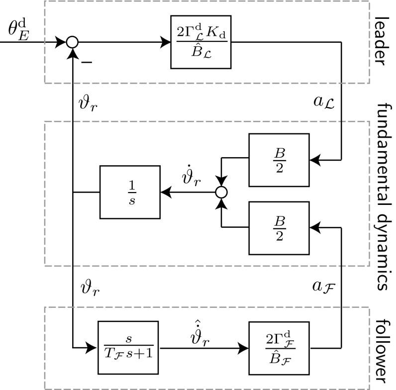
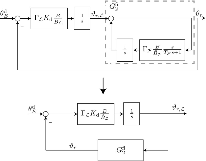
Here, we analyze stability, stationary transfer behavior and resultant follower contribution for filtered energy flow estimates and estimation errors on the follower and leader side. Figure 7 shows a block diagram of the fundamental energy dynamics-based control structure for a leader and a follower controller. See “Appendix C” for details on the derivations of the transfer functions.
Fig. 7.
Block diagram showing the leader and follower controllers interacting with the linear fundamental energy dynamics. The leader tracks first-order reference dynamics with inverse time-constant to control the energy to with a desired relative energy contribution . The follower achieves a desired relative energy contribution by imitating an estimate of the system energy flow
The reference transfer function , which describes the closed-loop behavior resulting from the interconnection depicted in Fig. 7, results in
| 27 |
Thus, and we have a stationary transfer behavior equal to one for a step of height in the reference variable . This result holds irrespective of estimation errors . Asymptotic stability of the closed-loop system is ensured for . The stability constraint implies that is advantageous. This can be achieved by using a high initial value in the follower’s -estimation for the abstract cart-pendulum and a low initialization for the abstract torque-pendulum (see (18)). Factors such as estimation errors, a high desired follower contribution and a small time constant can potentially destabilize the closed-loop system.
The follower transfer function from desired energy level to follower energy is
| 28 |
Application of the final value theorem to (28) yields . Consequently, and the follower achieves its desired relative energy contribution for a correct estimate .
Application to Two-Agent Object Manipulation
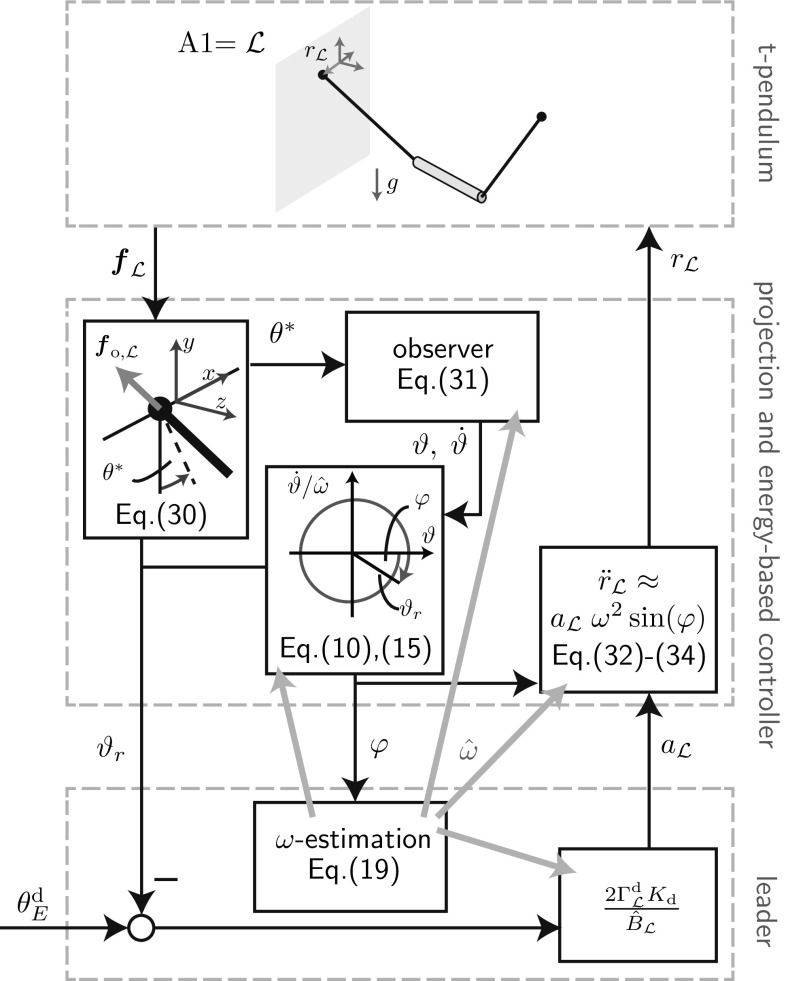
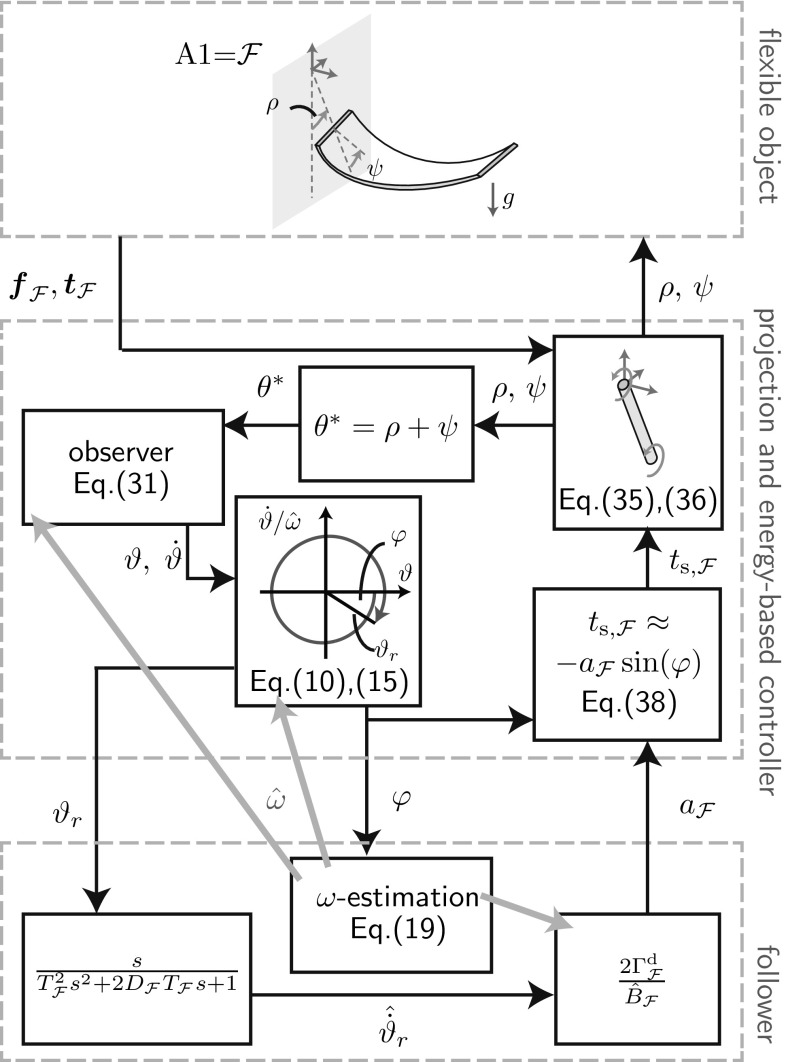
Here, we extend the fundamental dynamics (FD)-based adaptive controllers presented in the previous section to control the t-pendulum and the afa-system. Figures 8 and 9 show block diagrams of the controller implementation for the t-pendulum controlled by a leader agent and the afa-system controlled by a follower agent, respectively. Follower and leader controllers are invariant with respect to the object types. In Sect. 6.1, we discuss modifications of the fundamental dynamics-based controllers to cope with modeling errors. The projection and energy-based controller block differs between the t-pendulum and the afa-system and will be explained in detail in Sects. 6.2 and 6.3, respectively.
Fig. 8.
Block diagram of the FD-based leader applied to the t-pendulum
Fig. 9.
Block diagram of the FD-based follower applied to the afa-system
FD-Based Controllers
The FD derivation is based on approximating the system energy by the phase space radius in Sect. 4.4. As visible in the phase space on the left side of Fig. 5, the phase space radius represents the system energy less accurately at higher energy levels. The effect is increased oscillations of for constant . As a consequence, unsettled follower behavior is expected even when the leading partner is trying to keep the system energy at a constant level. Furthermore, the discrepancy between and degrades the leader’s reference dynamics tracking ability.
From and we can estimate based on (8). To this end, we use the geometric mean relationship in (9) with current frequency estimate and solve it for the unknown small angle approximation . Insertion of into (8) results in a quadratic equation which we solve for
| 29 |
The estimate can now be used instead of within the leader and follower controllers.
Interestingly, the error caused by the phase space radius approximation has a greater influence on the abstract torque-pendulum than on the abstract cart-pendulum. Because in (13) and reach their maxima for , the torque-based actuation contributes maximum energy when the error between and has its maximum (see Fig. 5). In contrast, the acceleration-based actuation in (12) contributes most energy when the multiplication of velocity and applied force in x-direction reach a maximum, where has its maximum at . We will show the implications of above discussion and the usage of based on simulations of the abstract simple pendulums in Sect. 7.
The realistic pendulum-like and flexible object do not exhibit perfect simple pendulum-like behavior. As we show with our experimental results in Sect. 8, such unmodeled dynamics have only little effect on the leader controller performance. In order to achieve calm follower behavior during constant energy phases, we use a second-order low-pass filter along with the differentiation of for the experiments instead of the first-order low-pass filter (compare Figs. 7, 9). Besides the extension by the -estimation, the second-order filter for the follower is the only modification we apply to the FD-based controllers in Fig. 7 for the experiments. Because we are limited to relatively small energies for the afa-system where , use of the more accurate estimate is not needed.
At small energy levels, noise and offsets in the force and torque signals can lead to a phase angle that does not monotonically increase over time. We circumvented problems with respect to the -estimation by reinitializing whenever decreased below a small threshold. No modifications were needed for the amplitude factor computation.
The computation of the FD parameter B in (18) requires a moment of inertia estimate . For the experiments, we computed based on known parameters of the simple pendulum-like arm and based on a point mass approximation of the flexible object . The part of the object mass carried by the robot is measured with the force sensor. We furthermore assume that an estimate of the projected object length is available. Alternatively, the object moment of inertia could be estimated from force measurements during manipulation (e.g., [3, 27]).
Projection and Energy-Based Controller for the t-Pendulum
Projection onto the Abstract Cart-Pendulum
The goal of what we call the projection onto the abstract cart-pendulum, is to extract the desired oscillation from the available force measurements . The projection is performed in two steps. First, the projected deflection angle is computed from
| 30 |
with being the force exerted by agent A1 onto the pendulum-like object. We obtain from the measurable applied force through dynamic compensation of the force accelerating the handle mass : .
The projected deflection angle does not only contain the desired -oscillation, but is superimposed by undesired oscillations, such as the -oscillation in Fig. 3. In a second step, we apply a nonlinear observer to extract the states of the virtual abstract cart-pendulum
| 31 |
where couples the observer to the t-pendulum through the observer gain vector . The observer does not only filter out the undesired oscillation , but also noise in the force measurement. An observer gain in the range of showed to yield a good compromise between fast transient behavior (large ) and noise filtering (small ). The smooth cartesian cart-pendulum states can then be transformed into polar states according to (10) and (15). The observer represents the abstract cart-pendulum dynamics (4) without inputs. Simulations and experiments showed that it suffices to use as the estimate for the small angle approximation needed in (31). We summarize these two steps as projection onto the abstract cart-pendulum.
Complete Control Law for the t-Pendulum
As suggested in [48], we do not directly command the acceleration in (12). Instead, we filter out remaining high frequency oscillations on the phase angle through application of a second-order filter
| 32 |
with design parameters and , to the reference trajectory
| 33 |
The acceleration results in
| 34 |
Hence, we make use of the sinusoidal shape of by including knowledge on the expected phase shift and amplitude shift at . Use of position as a reference for the robot low-level controller circumvents drift. Furthermore, by imposing limits on , the workspace of the robot can be limited [13, 48].
Projection and Energy-Based Controller for the afa-System
Simple Pendulum-like Arm
Based on the results of [15], we model the robot end effector to behave as a cylindrical simple pendulum with human-like parameters of shoulder damping , mass , length and density for the experiments with a robotic manipulator in Sect. 8. The robot arm dynamics are
| 35 |
where is the arm moment of inertia with respect to the shoulder and and are torques around the z-axis of coordinate system caused by gravity and the applied interaction forces at the wrist , respectively. The wrist joint dynamics are
| 36 |
with moment of inertia , damping and stiffness . The z-component of applied torque is measured at the interaction point with the flexible object.
Projection onto the Abstract Torque-Pendulum
We base the projection of the afa-system onto the abstract torque-pendulum on a simple summation and the observer with simple pendulum dynamics in (31).
Complete Control Law for the afa-System
No additional filtering is applied for the computed shoulder torque. However, the wrist damping dissipates energy injected at the shoulder. The energy flow loss due to wrist damping is . We approximate the injected energy flow at the shoulder as
| 37 |
where we inserted according to (13), used of (16) and approximated by its mean. Setting yields amplitude factor for wrist damping compensation.
For the experiments, we add human-like shoulder damping to the passive arm behavior. During active follower or leader control the shoulder damping is compensated for by an additional shoulder torque of . The complete control law results in
| 38 |
Evaluation in Simulation
The linear fundamental dynamics (FD) derived in Sect. 4 enabled the design of adaptive leader and follower controllers in Sect. 5. However, the FD approximates the behavior of the abstract cart- and torque-pendulums, which represent the desired oscillations of the t-pendulum and the afa-system. In this section, we analyze the FD-based controllers in interaction with the abstract cart- and torque-pendulums with respect to stability of the -estimation (Sect. 7.3), reference trajectory tracking (Sect. 7.4) and follower contribution (Sect. 7.5). For simplicity, we assume full state feedback and use the variables and also for the abstract cart- and torque-pendulums.
Simulation Setup
The simulations were performed using MATLAB/Simulink. We modeled the cart-pendulum as a point mass attached to a massless pole of length . The torque-pendulum consisted of two rigidly attached cylinders with uniform mass distribution. The upper cylinder was of mass, density and length comparable to a human arm: [7], [11], [15]. The lower cylinder had the same radius, but mass and length .
The following control gains stayed constant for all simulations , , , . We started all abstract cart- and torque-pendulum simulations with a small angle and zero velocity in order to avoid initialization problems, e.g., of the phase angle .
Measures
Analysis of Controller Performance
We analyzed the controller performance based on settling time , steady state error e and overshoot o. The settling time was computed as the time after which the energy stayed within bounds around the energetic steady state value . We defined the steady state error as and the overshoot as .
Analysis of Effort Sharing
The energy flows to the abstract cart-pendulum were calculated based on velocities and applied force along the motion , where . The energy flows to the abstract torque-pendulum were calculated based on angular velocity and applied torque , where . The multiplication with reflects that the agents equally share the control over the abstract pendulums in (4) and (5).
We based the analysis of the effort sharing between the agents on the relative energy contribution of the follower . The definition in (2) is based on the time derivative of the oscillation amplitude and , which requires use of the simple pendulum approximations. In order not to rely on approximations, we define the relative follower contribution
| 39 |
The above computation has the drawback that for mechanisms with high damping , because the follower reacts to changes in object energy and, thus, the leader accounts for damping compensation. Therefore, we define a second relative follower contribution based on the object energy E for comparison
| 40 |
For the abstract simple pendulums we use . Note that for a damped mechanism.
Stability Limits of the -Estimation
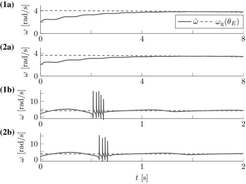
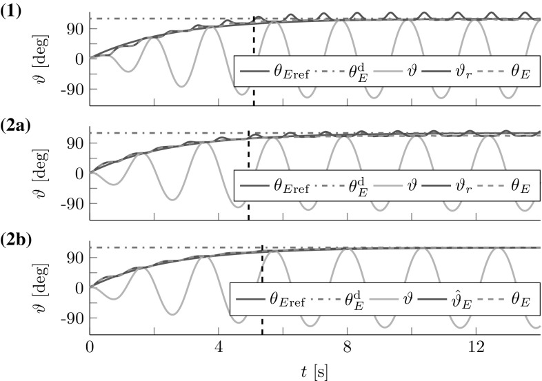
The FD analysis in Sect. 5.1 revealed the theoretical stability bound (20). Here, we test its applicability to the cart- and torque-pendulums with energy dependent natural frequency . Both lossless pendulums were controlled by one leader with constant amplitude factor for the cart-pendulum and for the torque-pendulum. The amplitude factors were chosen, such that for both pendulums approximately an energy level of was reached after 8 s. Figure 10 shows the geometric mean approximation of the natural frequency and the estimate for two different time constants and . The results support the conservative constraint found from the Lyapunov stability analysis in Sect. 5.1.
Fig. 10.
Natural frequency estimation for the (1a–b) cart-pendulum and (2a-b) torque-pendulum: (a) the estimate smoothly approaches the geometric mean approximation of the natural frequency for an estimation time constant , (1b) first signs of instability occur for for the cart-pendulum and (2b) for for the torque-pendulum. Note the different time and natural frequency scales. This result is in accordance with the theoretically found conservative stability bound which evaluates to for
Reference Dynamics Tracking
Here, we evaluate how well reference dynamics tracking is achieved for a single leader interacting with the cart- and torque-pendulums, thus . In order to focus on the reference dynamics tracking, we used the geometric mean with exact in (9) as an accurate natural frequency estimate for the leader controller. We set and 3. The results for the lossless pendulums are displayed in Fig. 11. The simulation results support the considerations made in Sect. 6.1.
Fig. 11.
Reference dynamics tracking for (1) cart-pendulum and (2a) torque-pendulum based on energy equivalent with and , respectively. Usage of an estimate instead of reduces the steady state error for the torque-pendulum to (2b). Vertical dashed lines mark settling times
Follower Contribution
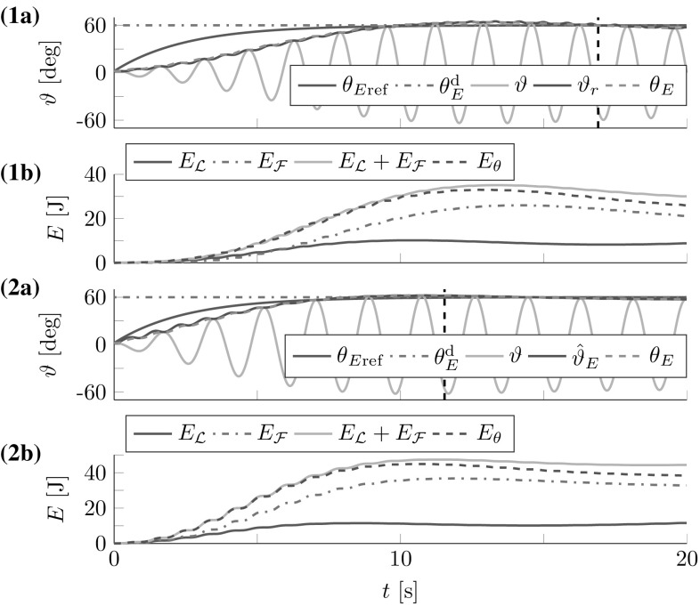
For the follower contribution analysis, we ran simulations with a leader and a follower interacting with the abstract cart- and torque-pendulums for different desired relative follower contributions . The pendulums were slightly damped with and . The leader’s desired energy level was . In accordance with the stability analysis in Sect. 5.3, we initialized the -estimation with for the abstract cart-pendulum and for the abstract torque-pendulum. The follower and leader controllers for the torque-pendulum made use of the approximation in (29) instead of in (21) and (26).
The first three lines of Table 2 list the results for , including the relative follower contributions according to (39) and (40) and the overshoot o. Figure 12 shows angles and energies over time for the most challenging case of . The damping resulted in increased steady state errors of for the abstract cart-pendulum and for the abstract torque-pendulum. The -estimation and filtering for the energy flow estimate on the follower side caused a delay with respect to the reference dynamics . With respect to effort sharing, higher resulted in increased overshoot o (see Table 2). Successful effort sharing was achieved, with .
Table 2.
Effort sharing results
| Abstr. cart-pend. | Abstr. torque-pend. | |||||
|---|---|---|---|---|---|---|
| 0.3/0.7 | 0.9 | 0.27 | 0.27 | 0.1 | 0.33 | 0.33 |
| 0.5/0.5 | 3.2 | 0.45 | 0.47 | 1.1 | 0.52 | 0.54 |
| 0.7/0.3 | 8.7 | 0.75 | 0.84 | 4.9 | 0.78 | 0.82 |
| 0.3/0.3 | 0.1 | 0.30 | 0.32 | 0.1 | 0.31 | 0.33 |
| 0.7/0.7 | 9.6 | 0.81 | 0.87 | 6.5 | 0.86 | 0.90 |
Fig. 12.
Simulated follower and leader interacting with the (1) abstract cart-pendulum and (2) abstract torque-pendulum for a desired relative follower contribution : (a) angles and (b) energies. Vertical dashed lines mark settling times . The FD-based controllers allow for successful effort sharing
The last two lines of Table 2 list the results for . The results conform to the FD analysis in Sect. 5.3: with . The transient behavior is predominantly influenced by . Low (high) values yield slower (faster) convergence to the desired energy level with small (increased) overshoot o. An increased o comes along with increased transient behavior that settles only after . As a consequence, and exceed .
Experimental Evaluation
The simulations in Sect. 7 analyze the presented control approach for the abstract cart- and torque-pendu- lum. In this section, we report on the results of real world experiments with a t-pendulum and a flexible object which test the controllers in realistic conditions: noisy force measurements, non-ideal object and robot behavior and a human interaction partner. Online Resources 1 and 2 contain videos of the experiments.
Experimental Setup
Hardware Setup
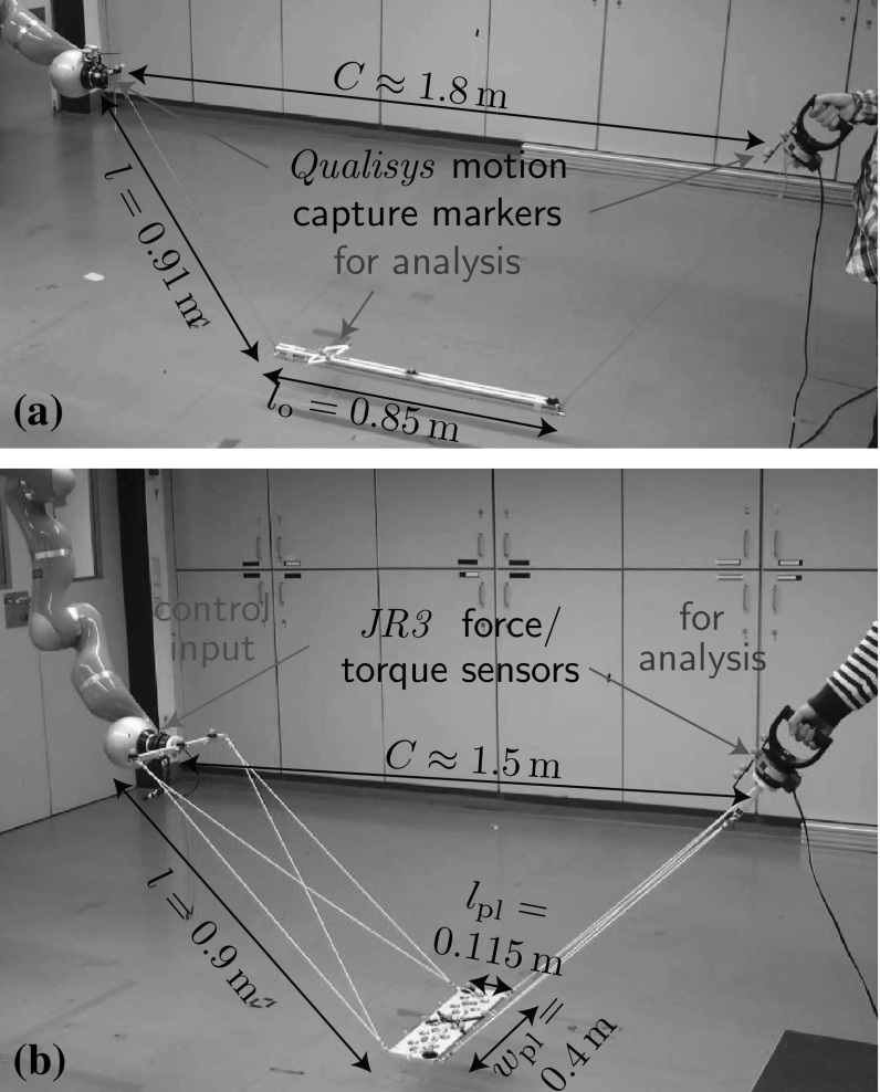
Figure 13 shows the experimental setups with pendulum-like and flexible objects. Due to the small load capacity of the robotic manipulator4, we used objects of relatively small mass for the t-pendulum and for the flexible object. The flexible object was composed of an aluminum plate connected to two aluminum bars through rubber bands. Such flexible object can be seen as an especially challenging object as it only loosely couples the agents and its high elasticity can cause unwanted oscillations.
Fig. 13.
Experimental setups for (a) pendulum-like and (b) flexible object swinging: One side of the objects was attached to the end effector of a KUKA LWR 4+ robotic manipulator under impedance control on joint level (joint stiffness 1500 Nm/rad and damping 0.7 Nm s/rad). The other side was attached to a handle that was either fixed to a table or held by the human interaction partner
Software Implementation
The motion capture data was recorded at 200 Hz and streamed to a MATLAB/Simulink Real-Time Target model. The Real-Time Target model was run at 1 kHz, received the force/torque data and contained the presented energy-based controller and the joint angle position controller of the robotic manipulator. For the analysis, we filtered the motion capture data and the force/torque data by a third-order butterworth low-pass filter with cutoff frequency 4 Hz.
The following control parameters were the same for all experiments , , , , and . The -estimation used a time constant and was initialized to for the t-pendulum. For the flexible object swinging, we controlled the robot to behave as a simple pendulum (see Sect. 6.3) with human arm parameters given in Sect. 7.1. The wrist parameters were , , . The projected object length estimate needed for the approximation of the abstract torque-pendulum moment of inertia was set to . The -estimation used a time constant and was initialized to .
Measures
We used the same measures to analyze the experiments as for the simulations in Sect. 7.2. Extensions and differences are highlighted in the following.
Analysis of the Projections onto the Abstract Cart- and Torque-Pendulums
Ideally, during steady state, the disturbance oscillations is close to zero , the abstract pendulum angle should be close to the actual object deflection and the energies should match . From motion capture data we obtained and for the t-pendulum . The undesired oscillation of the afa-system is the known wrist angle . From , its numerical time derivative and , the energy equivalent was computed.
Analysis of Effort Sharing
The energy flows of the agents were calculated based on with , interaction point rotational velocities and for the t-pendulum. The energy contained in the object was calculated based on object height and object twist
| 41 |
The mass matrix is composed of a diagonal matrix with the object mass as diagonal entries and a moment of inertia tensor . The t-pendulum object moment of inertia was approximated as a cylinder with uniform mass distribution of diameter . For the afa-system, we neglected energy contained in the rubber bands and the aluminum bars attached to the force/torque sensors and computed the energy contained in the aluminum plate of mass and thickness under the simplifying assumption of uniform mass distribution (see Fig. 13 for further dimensions). Above variables are expressed in a fixed world coordinate system translated such that for . The energy contained in undesired system oscillations can be approximated as .
Experimental Controller Evaluation for the t-Pendulum
We present results for three t-pendulum experiments: maximum achievable energy (Sect. 8.3.1), active follower contribution (Sect. 8.3.2) and excitation of undesired -oscillation (Sect. 8.3.3).
Maximum Achievable Energy (Robot Leader and Passive Human)
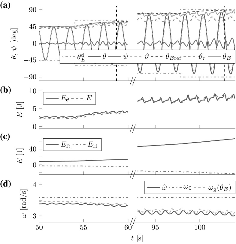
The limitations of the controller with respect to the achievable energy levels were tested with a robot leader . A human passively held the handle of agent in order to avoid extreme -oscilla- tion excitation at high energy levels due to a rigid fixed end. The t-pendulum started from rest (). The desired energy level was incrementally increased from 15 deg to 90 deg. The desired relative energy contribution of the robot was .
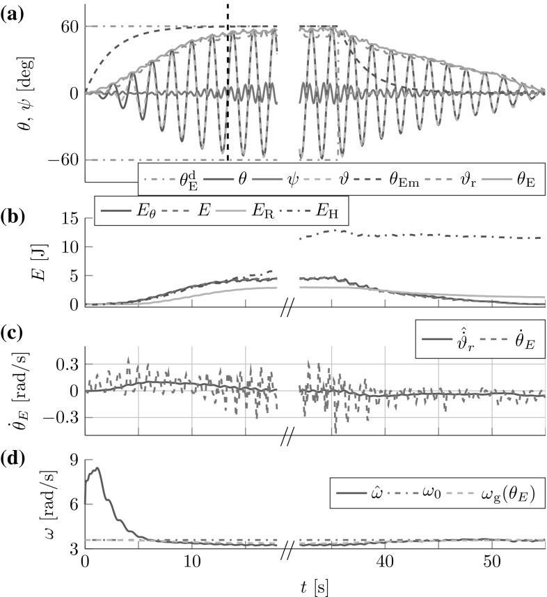
The robot successfully controlled the t-pendulum energy to closely follow the desired reference dynamics (see Fig. 14).
Fig. 14.
Maximum achievable energies for the t-pendulum: (a) deflection angles and energy equivalents, (b) energies contained in the t-pendulum and (c) contributed by the human and the robot (d) natural frequency estimates. Vertical dashed lines mark settling times . A robot leader can reach deflection angles in interaction with a passive human
The steady state error increased with higher desired energy due to increased damping, e.g., at and at . The energy contained in the undesired oscillation increased from at to at and was, thus, kept in comparably small ranges. With increased -oscillation, the t-pendulum behaves less simple pendulum-like, which also becomes apparent in an increased difference between and . The successful reference dynamics tracking and close estimate for smaller and intermediate energy levels and the close -estimation support the applicability of the fundamental dynamics (FD)-based leader controller.
Active Follower Contribution (Robot Follower and Human Leader)
A robot follower with interacted with a human leader . The t-pendulum started from rest (). The human leader was asked to first inject energy to reach , to hold the energy constant and finally to release the energy from the pendulum again. The desired energy limit was displayed to the human via stripes of tape on the floor to which the pendulum mass had to be aligned to at maximum deflection angles.
The human–robot team successfully injected energy until was reached with (see Fig. 15). Similar to the simulations, the reference dynamics were tracked with a delay. The undesired oscillation increased, but did not exceed . The object energy flow highly oscillated, which is in accordance with the results from human–human rigid object swinging [15]. The robot successfully detected and imitated the object energy flow. During the 20 s constant energy phase, the human compensated for energy loss due to damping. The relative energy contributions and were close to the desired . The follower controller highly depends on the FD approximation. Thus, the successful energy sharing between a human leader and a robot follower further supports the efficacy of the FD-based controllers to human–robot dynamic object manipulation.
Fig. 15.
Robot follower cooperatively injecting energy into the t-pendulum with a human leader: (a) deflection angles and energy equivalents, (b) energies contained in the t-pendulum and contributed by the human and the robot, (c) actual and estimated energy flows, (d) natural frequency estimates. The vertical dashed line marks settling time
Excitation of Undesired -Oscillation (Robot Leader and Fixed End)
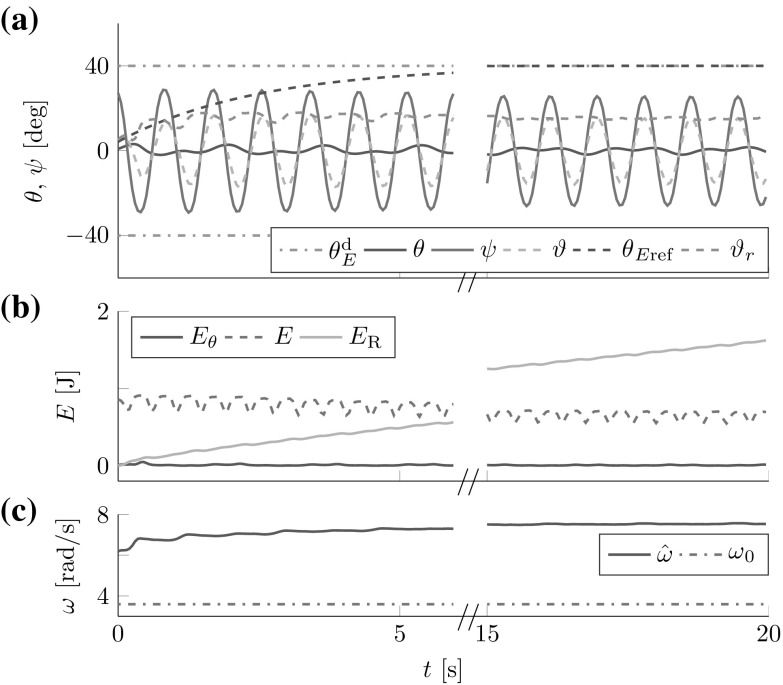
The pendulum mass was manually released in a pose with high initial -oscillation , but . A goal energy of was given to the robot leader with , while the handle of agent was fixed.
The robot identified the natural frequency of the -oscillation and tried to inject energy to reach the desired amplitude of (see Fig. 16). Thus, the robot failed to excite the desired -oscillation and keep unwanted oscillations in small bounds as defined in Sect. 3. However, considering the controller implementation given in Fig. 8, this experimental result supports the correct controller operation: the -estimation identified the frequency of the current oscillation, here the undesired -oscillation. Based on , the leader controller was able to inject energy into the -oscillation; not enough to reach the desired amplitude of , but enough to sustain the oscillation. Note that the -oscillation is highly damped, less simple pendulum-like and in general more difficult to excite than the -oscillation. Experiments with a controller that numerically differentiates the projected deflection angle , instead of using the observer, less accurately timed the energy injection. The result was a suppression of the -oscillation through natural damping until the -oscillation dominated and was reached.
Fig. 16.
Strong initial for robot leader and fixed end: (a) deflection angles and energy equivalents, (b) energies contained in the t-pendulum and contributed by the robot, (c) natural frequency estimates. The robot detected the natural frequency of the less simple pendulum-like -oscillation and sustained it
On the one hand side, this experiment supports the control approach by showing that the controller is able to excite also less simple pendulum-like oscillations. On the other hand side, this experiment reveals the need for a higher level entity to detect failures as when the wrong oscillation is excited (see the discussion in Sect. 9.1).
Experimental Controller Evaluation for the afa-System
Joint velocity limitations of the KUKA LWR restricted us to energies for the afa-system experiments. We present experiments that investigate the maximum achievable energy (Sect. 8.4.1) and active follower contribution (Sect. 8.4.2).
Maximum Achievable Energy (Robot Leader and Passive Human)
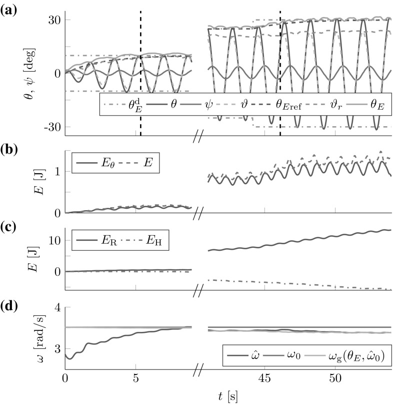
A robot leader interacted with a passive human leader under the same conditions as for the t-pendulum in Sect. 8.3.1. We incrementally increased from 10 deg to 30 deg.
The robot leader closely followed the desired reference dynamics and achieved small steady state errors, e.g., at and at (see Fig. 17). Undesired oscillations at the wrist stayed below . The projection of the flexible object onto the abstract torque-pendulum was performed based on the sum and the simple pendulum observer. From Fig. 4 it seems like the sum overestimates the deflection angle at the shoulder. However, the known wrist angle only reflects the orientation of the flexible object at the robot interaction point. The flexibility of the object caused greater deflection angles . Consequently, the abstract torque-pendulum energy equivalent closely followed the energy equivalent at small energies, but underestimated for increased energies. Nevertheless, the results are promising as they show that a controlled swing-up was achieved based on the virtual energy of the abstract torque-pendulum.
Fig. 17.
Maximum achievable energies are limited to for the afa-system, due to joint velocity limits: (a) deflection angles and energy equivalents, (b) energies contained in the flexible object and (c) contributed by the human and the robot, (d) natural frequency estimates. Vertical dashed lines mark settling times
Active Follower Contribution (Robot Follower and Human Leader)
A robot follower interacted with a human leader under the same conditions as for the t-pendulum in Sect. 8.3.2. Due to the hardware limitations we used , but chose a higher and thus more challenging desired relative energy contribution of the robot follower of .
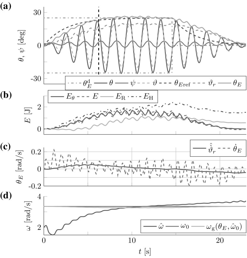
The robot successfully imitated the object energy flow, which led to human–robot cooperative energy injection to with small (see Fig. 18). The human first injected energy into the passive robot arm which is equivalent to the robot initially withdrawing some energy from the object, before the robot can detect the object energy increase. Therefore and due to the filtering for , the follower achieved only and , when evaluated at . However, the relative follower contribution increased and reached, e.g., and at . Interestingly, the energy contribution of the human and the robot were of similar shape, both for a robot follower and a robot leader. Thus, the simple pendulum-like behavior of the robot end effector allows to replicate human whole-arm swinging characteristics.
Fig. 18.
Robot follower cooperatively injecting energy into the flexible object with a human leader: (a) deflection angles and energy equivalents, (b) energies contained in the flexible object and contributed by the human and the robot, (c) actual and estimated energy flows, (d) natural frequency estimates. The energy contributions of the robot and the human show similar characteristics. The vertical dashed line marks settling time
Discussion
Embedding of Proposed Controllers in a Robotic Architecture
One of the major goals of robotics research is to design robots that are able to manipulate unknown objects in a goal-directed manner without prior model knowledge or tuning. Robot architectures are employed to manage such complex robot functionality [42]. These architectures are often organized in three layers: the lowest layer realizes behaviors which are coordinated by an intermediate executive layer based on a plan provided by the highest layer. In this work, our focus is on the lowest layer: the behavior of cooperative energy injection into swinging motion, which is challenging in itself due to the underactuation caused by the multitude of DoFs of the pendulum-like and flexible objects. On the behavioral layer, we use high-frequency force and torque measurements to achieve continuous energy injection and robustness with respect to disturbances. The controllers presented implement the distinct roles of a leader and a follower. As known from human studies, humans tend to specialize, but do not rigidly stick to one role and continuously blend between leader and follower behaviors [40]. Role mixing or blending would be triggered by the executive layer. The executive layer would operate at a lower frequency and would have access to additional sensors as, e.g., a camera that allows to monitor task execution. Based on the additional sensor measurements, exceptions could be handled (e.g., when a wrong oscillation degree of freedom is excited as in Sect. 8.3.3), the required swinging amplitude could be set and behavior switching could be triggered (e.g., from the object swing-up behavior to an object placement behavior).
Furthermore, additional object specific parameters could be estimated on the executive layer, as, e.g., damping or elastic object deformation. The fundamental dynamics (FD) approach does not model damping, and consequently indicates that the controller exhibits the desired behavior. However, that also means that , because the leader compensates for damping. As all realistic objects exhibit non negligible damping, an increased robot contribution during swing-up can be achieved by increasing . The desired relative energy contribution could thus serve as a single parameter that could, for instance, be adjusted online by the executive layer to achieve a desired robot contribution to the swing-up. Alternatively to an executive layer, a human partner could adjust a parameter as online to achieve desired robot follower behavior and could also assure excitation of the desired oscillation.
Generalizeability
The main assumption made in this work is that the desired oscillation is simple pendulum-like. Based on this assumption, the proposed approach is generalizable in the sense that it can be directly applied to the joint swing-up of unknown objects without parameter tuning5 (see video with online changing flexible object parameters in Online Resource 2). We regard the case of a robotic follower interacting with a human leader as an interesting and challenging scenario and therefore presented our method from the human–robot cooperation perspective. Nevertheless, the proposed method can also directly be employed for robot-robot teams or single robot systems as, e.g., quadrotors and can also be used to damp oscillations instead of exciting them. The task of joint energy injection into a flexible bulky object might appear to be a rare special case. However, it is a basic dynamic manipulation skill that humans possess and should be investigated in order to equip robots with universal manipulation skills.
We see the main take away message for future research from this work in the advantage of an understan- ding of the underlying FD. Based on the FD that encodes desired behavior, simple adaptive controllers can be designed and readily applied to complex tasks even when task parameters change drastically, as, e.g., when objects of different dimensions have to be manipulated.
Dependence of Robot Follower Performance on the Human Interaction Partner
Performance measures as settling time and steady state error e strongly depend on the behavior of the human partner. The robot follower is responsible for the resultant effort sharing. Ideally, the robot follower contributes with the desired fraction to the current change in object energy at all times . Necessary filtering and the approximations made by the FD do result in a delayed follower response and deviation from . However, for the follower, we do not make any assumptions on the way how humans inject energy into the system, e.g., we do not assume that human leaders follow the desired reference dynamics that we defined for robot leaders. This is in contrast to our previous work [13], where thresholds were tuned with respect to human swing-up behavior and the follower required extensive model knowledge to compute the energy contained in the oscillation. For demonstration purposes, we aimed for a smooth energy injection of the human leader for the experiments presented in the previous section. Energy was not injected smoothly to match modeled behavior, but only to enable the use of measures as the relative energy contribution at the settling time for effort sharing analysis.
Alternatives to Energy-Based Swing-Up Controllers
Energy-based controllers as [48] are known to be less efficient than, e.g., model predictive control (MPC)-based controllers [31]. MPC can improve performance with respect to energy and time needed to reach a desired energy content. However, in this work, we do not aim for an especially efficient robot controller, but for cooperative energy injection into unknown objects. Use of MPC requires a model, including accurate mass and moment of inertia properties. Use of the energy-based controller of [48] allows to derive the FD as an approximate model. The FD reduces the unknowns to the natural frequency and moment of inertia estimate for the afa-system, which can be estimated online. Design of a follower controller is only possible, because the FD allows for a comparison of expectation to observation. How to formulate the expectation for an MPC-based approach is unclear and would certainly be more involved. The great advantage of the FD -based approach lies in its simplicity.
Alternative Parameter Estimation Approaches
In this work, the goal of a leader controller is to track desired reference dynamics. Such behavior could also be achieved by employing model reference adaptive control (MRAC) [2] or by employing filters to compare applied amplitude factors a to the achieved energy increase to estimate the unknown FD parameter B. The disadvantage of MRAC and other approaches is that they need to observe the system energy online to estimate the system constant B. Having more than one agent interacting with the system does not only challenge the stability properties of MRAC, but also makes it impossible to design a follower that requires to differentiate between its own and external influence on .
The FD approximates the system parameter B by its mean, while the true value oscillates. The mean parameter B depends on the natural frequency , which can be approximated by observing the phase angle . Because the FD states and are approximately decoupled, reference dynamics tracking and energy flow imitation can be achieved for unknown objects.
The natural frequency could also be estimated by observing the time required by a full swing. Decrease of the observation period yields the continuous simple low-pass filter used in this article. Alternatively, the desired circularity of the phase space could be used to employ methods such as gradient descent [37] or Newton Raphson to estimate . We chose the presented approach for its continuity and simplicity, as well as its stability properties with respect to the FD assumption.
Stability of Human–Robot Object Manipulation
We proved global stability of the presented control approach for the linear FD. Stability investigations of the human–robot flexible object manipulation face several challenges. Firstly, dynamic models of the complex t-pendulum and afa-system would be required. Furthermore, the human interaction partner acts as a non-autonomous and non-reproducible system that is difficult to model and whose stability cannot be analyzed based on common methods [5]. In [23], Hogan presents results that indicate that the human arm exhibits the impedance of a passive object; however, this result cannot be directly applied to show stabilization of limit cycles, as the simple pendulum oscillation in this work, for a passivity-based stability analysis [24]. A stability analysis of the simpler, but nonlinear abstract simple pendulums requires a reformulation of the system dynamics in terms of the errors and . The lack of analytic solutions for [6] and (see Sect. 4.4) impede the derivation of above error dynamics.
As our final goal is cooperative dynamic human–robot interaction, we refrained from further stability investigations in this paper and focused on simulation- and experiment-based analyses. The simulations and human–robot experiments suggest that the domain of attraction of the presented FD-based controllers is sufficiently large to allow for cooperative energy injection into nonlinear high energy regimes.
Conclusions
This article presents a control approach for cooperative energy injection into unknown flexible objects as a first step towards human–robot cooperative dynamic object manipulation. The simple pendulum-like nature of the desired swinging motion allows to design adaptive follower and leader controllers based on simple pendulum closed-loop fundamental dynamics (FD). We consider two different systems and show that their desired oscillations can be approximated by similar FD. Firstly, a pendulum-like object that is controlled via acceleration by the human and the robot. Secondly, an oscillating entity composed of the agents’ arms and a flexible object that is controlled via torque at the agents’ shoulders. The robot estimates the natural frequency of the system and controls the swing energy as a leader or follower from haptic information only. In contrast to a leader, a follower does not know the desired energy level, but actively contributes to the swing-up through imitation of the system energy flow. Experimental results showed that a robotic leader can track desired reference dynamics. Furthermore, a robot follower actively contributed to the swing-up effort in interaction with a human leader. High energy levels of swinging amplitudes greater than were achieved for the pendulum-like object. Although joint velocity limits of the robotic manipulator restricted swinging amplitudes to for the “arm—flexible object—arm” system, the experimental results support the efficacy of our approach to human–robot cooperative swinging of unknown flexible objects.
In future work, we want to take a second step towards human–robot cooperative dynamic object manipulation by investigating controlled object placement as the phase following the joint energy injection. Furthermore, we are interested in applying the presented technique of approximating the desired behavior by its FD to different manipulation tasks.
Electronic supplementary material
Below is the link to the electronic supplementary material.
Acknowledgements
The research leading to these results has received funding partly from the European Research Council under the European Unions Seventh Framework Programme (FP/2007-2013) / ERC Grant Agreement no. [267877] and partly from the Technical University of Munich - Institute for Advanced Study (www.tum-ias.de), funded by the German Excellence Initiative.
Biographies
Philine Donner
received the diploma engineer degree in Mechanical Engineering in 2011 from the Technical University of Munich, Germany. She completed her diploma thesis on “Development of computational models and controllers for tendon-driven robotic fingers” at the Biomechatronics Lab at Arizona State University, USA. From October 2011 to February 2017 she worked as a researcher and Ph.D. student at the Technical University of Munich, Germany, Department of Electrical and Computer Engineering, Chair of Automatic Control Engineering. Currently she works as a research scientist at Siemens Corporate Technology. Her research interests are in the area of automatic control and robotics with a focus on control for physical human–robot interaction.
Franz Christange
graduated with B.Sc. and M.Sc. in Electrical Engineering, in the field of control theory and robotics at Technical University of Munich, Germany in 2014. Currently he works as a researcher at the Technical University of Munich, Germany, Department of Electrical and Computer Engineering, Chair of Renewable and Sustainable Energy Systems. His research focuses on intelligent control of distributed energy systems.
Jing Lu
received the Bachelor Degree in Control Engineering from University of Kaiserslautern, Germany and from Fuzhou University, China in 2014. She received the Master Degree in Automatic Control and Robotics from the Technical University of Munich, Germany in 2016.
Martin Buss
received the Diplom-Ingenieur degree in Electrical Engineering in 1990 from the Technical University Darmstadt, Germany, and the Doctor of Engineering degree in Electrical Engineering from the University of Tokyo, Japan, in 1994. In 2000 he finished his habilitation in the Department of Electrical Engineering and Information Technology, Technical University of Munich, Germany. In 1988 he was a research student at the Science University of Tokyo, Japan, for 1 year. As a postdoctoral researcher he stayed with the Department of Systems Engineering, Australian National University, Canberra, Australia, in 1994/5. From 1995 to 2000 he has been senior research assistant and lecturer at the Institute of Automatic Control Engineering, Department of Electrical Engineering and Information Technology, Technical University of Munich, Germany. He has been appointed full professor, head of the control systems group, and deputy director of the Institute of Energy and Automation Technology, Faculty IV Electrical Engineering and Computer Science, Technical University Berlin, Germany, from 2000 to 2003. Since 2003 he is full professor (chair) and director of the Institute of Automatic Control Engineering, Department of Electrical and Computer Engineering, Technical University of Munich, Germany. From 2006 to 2014 he has been the coordinator of the DFG Excellence Research Cluster Cognition for Technical Systems CoTeSys. Martin Buss is a fellow of the IEEE. He has been awarded the ERC advanced grant SHRINE. From 2014 to 2017 he was a Carl von Linde Senior Fellow with the TUM Institute for Advanced Study. Martin Buss research interests include automatic control, haptics, optimization, nonlinear, hybrid discrete-continuous systems, and robotics.
Derivation of the Fundamental Dynamics
Application of the following three steps yields the dynamics of the abstract cart- and torque-pendulums (4), (5) in terms of the polar states :
Substitution of remaining cartesian states through polar states (16)
Step S1 applied to the phase angle requires the time derivative of the -function, which is
| 42 |
We get
| 43 |
| 44 |
with actuation terms for the abstract cart-pendulum
| 45 |
and for the abstract torque-pendulum
| 46 |
The resultant state space representations are control affine and coupled
| 47 |
with control input .
Insertion of the control laws (12) and (13) into and in (47) yield the state space representations with new inputs and of the form
| 48 |
Application of the following three steps to the state space representation (48) yields the fundamental dynamics (17):
-
S4Approximations through 3rd order Taylor polynomials:
-
S5Use of trigonometric identities:
And deduced from above: -
S6
Neglect of higher harmonics, e.g. ,
Use of the actual natural frequency for normalization of the phase space reduces the error caused by the approximations .
Phase dynamics :
| 49 |
with “” indicating application of the 3rd order Taylor approximation in reverse direction and insertion of the geometric mean approximation (9) with in the last step. For , the approximation steps S4 to S6 as detailed in (49) yield , independent of the actuation terms and . Consequently, the phase dynamics for the abstract cart- and torque-pendulums result in .
Energy dynamics : Similar to , the approximation steps S4 to S6 result in . The remaining term simplifies for the abstract cart-pendulum to
| 50 |
As for (49), we applied a reverse 3rd order Taylor approximation () and inserted the geometric mean approximation of the natural frequency in (9).
For the abstract torque-pendulum we get
| 51 |
Thus, the fundamental energy dynamics linearly depends on the amplitude factors . The result are the fundamental dynamics in (17).
Stability of the -Estimation
For an approximately constant natural frequency we have , where we set without loss of generality (see (11)). This yields the modified state transformations and compared to (16), and the phase computation results in
| 52 |
which is independent of . Consequently, the natural frequency estimation in Fig. 6 has one input, the natural frequency , and one output, the estimate . Note that we assume to be known only for the stability analysis, but not for the implementation displayed in Fig. 6.
In a next step, we derive the estimation dynamics in terms of its input and output . Differentiation of (52) with respect to time yields
| 53 |
Transformation of (19) into time domain yields
| 54 |
Insertion of (54) solved for into (53), followed by some rearrangements yields the -estimation dynamics
| 55 |
Because is bounded and constant, it suffices to show stability of the estimation error dynamics . As Lyapunov function we choose
| 56 |
with time derivative
| 57 |
For the numerator of (57) holds that if . The denominator is a quadratic function of , with . From we deduce that the denominator with is a convex parabola. Therefore, we have a positive denominator, if the discriminant is negative, i.e.
| 58 |
Condition (58) depends on the natural frequency estimate , which varies over time. Because we are estimating the natural frequency of a pendulum under the influence of gravity, only positive values are physically plausible . For and , we have and and initially approaches . If further , as long as and (58) can be rewritten as
| 59 |
Thus, if (59) holds, the -estimation is asymptotically stable under the fundamental dynamics assumption. This proves convergence of the estimate to the true value for a linearly oscillating pendulum.
Transfer Functions of Leader–Follower Structures
Rearrangement of the block diagram in Fig. 7 leads to the block diagram displayed in Fig. 19. The highlighted intermediate transfer function is
| 60 |
Based on (60) the reference input transfer function results in (27).
Fig. 19.
Rearranged block diagram for the computation of the transfer function :
For the computation of the relative follower contribution , consider the block diagram rearrangement in Fig. 20. From Fig. 20 with
| 61 |
we can compute the transfer function which yields the amount of energy the leader contributes based on the reference input
| 62 |
From with (27) and (62) we get in (28).
Fig. 20.
Rearranged block diagram for the computation of the energy contributed by the leader
Compliance with ethical standards
Conflicts of interest
The authors P. Donner, F. Christange, J. Lu and M. Buss declare that they have no conflict of interest.
Footnotes
We furthermore assume that a low-level robot control has access to the end effector position.
These oscillations can be damped through application of the controller presented in Sect. 5 in z-direction, as shown in [12] for the non-adaptive control approach of [13].
In contrast to the t-pendulum and the afa-system, the simple pendulum approximations are modeled as rigid and can thus reach oscillation amplitudes beyond . In order to challenge our approach, we command here.
The KUKA LWR 4+ can handle higher loads, if operated close to its singularities. However, joint velocity limits restrict the end effector velocity. As we are interested in a proof of concept of the proposed approach independent of the robotic platform used, we refrained from optimizing the robotic setup for higher loads and velocities.
Parameters were set once based on theoretic results (, ) or according to their physical meaning, i.e. they resemble filter coefficients (, , , , ), the human-like arm dynamics of the afa-system (, , , , ) or define desired leader/follower behavior (, ).
Contributor Information
Philine Donner, Email: [email protected].
Franz Christange, Email: [email protected].
Jing Lu, Email: [email protected].
Martin Buss, Email: [email protected].
References
- 1.Åström K, Furuta K. Swinging up a pendulum by energy control. Autom. 2000;36(2):287–295. doi: 10.1016/S0005-1098(99)00140-5. [DOI] [Google Scholar]
- 2.Åström KJ, Wittenmark B. Adaptive control. New York: Courier Corporation; 2013. [Google Scholar]
- 3.Atkeson CG, An CH, Hollerbach JM. Estimation of inertial parameters of manipulator loads and links. Int J Robot Res. 1986;5(3):101–119. doi: 10.1177/027836498600500306. [DOI] [Google Scholar]
- 4.Atkeson CG, Schaal S. Robot learning from demonstration. Proc Int Conf Mach Learn. 1997;97:12–20. [Google Scholar]
- 5.Burdet E, Tee KP, Mareels I, Milner TE, Chew CM, Franklin DW, Osu R, Kawato M. Stability and motor adaptation in human arm movements. Biol Cybern. 2006;94(1):20–32. doi: 10.1007/s00422-005-0025-9. [DOI] [PubMed] [Google Scholar]
- 6.Carvalhaes CG, Suppes P. Approximations for the period of the simple pendulum based on the arithmetic–geometric mean. Am J Phys. 2008;76(12):1150–1154. doi: 10.1119/1.2968864. [DOI] [Google Scholar]
- 7.Chandler R, Clauser CE, McConville JT, Reynolds H, Young JW (1975) Investigation of inertial properties of the human body. Technical report, DTIC Document
- 8.Cunningham D, Asada H (2009) The winch-bot: a cable-suspended, under-actuated robot utilizing parametric self-excitation. In: Proceedings of the IEEE international conference on robot automation, pp 1844–1850
- 9.de Crousaz C, Farshidian F, Buchli J (2014) Aggressive optimal control for agile flight with a slung load. In: IEEE/RSJ IROS workshop mach lern plan control robot motion
- 10.Deisenroth M, Fox D, Rasmussen C. Gaussian processes for data-efficient learning in robotics and control. IEEE Trans Pattern Anal Mach Intell. 2015;37(2):408–423. doi: 10.1109/TPAMI.2013.218. [DOI] [PubMed] [Google Scholar]
- 11.Dempster WT (1955) Space requirements for the seated operator. Technical report, Wright Air Development Center TH-55-159, Wright-Patterson Air Force Base, Ohio (AD 85 892)
- 12.Donner P, Buss M (2016b) Video: damping of in plane oscillations of the t-pendulum. http://www.lsr.ei.tum.de/fileadmin/w00brk/www/videos/Zdamping.mp4, Accessed 08 Mar 2017
- 13.Donner P, Buss M. Cooperative swinging of complex pendulum-like objects: experimental evaluation. IEEE Trans Robot. 2016;32(3):744–753. doi: 10.1109/TRO.2016.2560898. [DOI] [Google Scholar]
- 14.Donner P, Christange F, Buss M (2015) Fundamental dynamics based adaptive energy control for cooperative swinging of complex pendulum-like objects. In: Proceedings of the IEEE international conference on decision control, pp 392–399
- 15.Donner P, Wirnshofer F, Buss M (2014) Controller synthesis for human–robot cooperative swinging of rigid objects based on human–human experiments. In: Proceedings of the IEEE international symposium in robot human interact communication, pp 586–592
- 16.Doya K. Reinforcement learning in continuous time and space. Neural Comput. 2000;12(1):219–245. doi: 10.1162/089976600300015961. [DOI] [PubMed] [Google Scholar]
- 17.Evrard P, Kheddar A (2009) Homotopy switching model for dyad haptic interaction in physical collaborative tasks. In: Proceedings of the World Haptics Euro Haptics, pp 45–50
- 18.Fantoni I, Lozano R, Spong MW, et al. Energy based control of the pendubot. IEEE Trans Autom Control. 2000;45(4):725–729. doi: 10.1109/9.847110. [DOI] [Google Scholar]
- 19.Freidovich L, Robertsson A, Shiriaev A, Johansson R. Periodic motions of the pendubot via virtual holonomic constraints: theory and experiments. Automatica. 2008;44(3):785–791. doi: 10.1016/j.automatica.2007.07.011. [DOI] [Google Scholar]
- 20.Geravand M, Werner C, Hauer K, Peer A. An integrated decision making approach for adaptive shared control of mobility assistance robots. Int J Soc Robot. 2016;8(5):631–648. doi: 10.1007/s12369-016-0353-z. [DOI] [Google Scholar]
- 21.Groten R, Feth D, Klatzky R, Peer A. The role of haptic feedback for the integration of intentions in shared task execution. IEEE Trans Haptics. 2013;6(1):94–105. doi: 10.1109/TOH.2012.2. [DOI] [PubMed] [Google Scholar]
- 22.Hatsopoulos NG, Warren WH. Resonance tuning in rhythmic arm movements. J Mot Behav. 1996;28(1):3–14. doi: 10.1080/00222895.1996.9941728. [DOI] [PubMed] [Google Scholar]
- 23.Hogan N. Controlling impedance at the man/machine interface. Proc IEEE Int Conf Robot Autom. 1989;3:1626–1631. [Google Scholar]
- 24.Khalil HK, Grizzle J. Nonlinear systems. 3. Upper Saddle River: Prentice hall; 2002. [Google Scholar]
- 25.Kim CH, Yonekura K, Tsujino H, Sugano S (2009) Physical control of the rotation center of an unsupported object rope turning by a humanoid robot. In: Proceedings of the IEEE-RAS international conference on humanoid robots, pp 148–153
- 26.Kosuge K, Yoshida H, Fukuda T (1993) Dynamic control for robot-human collaboration. In: Proceedings of the IEEE international symposium in robot human interact communication, pp 398–401
- 27.Kubus D, Kroger T, Wahl FM (2008) On-line estimation of inertial parameters using a recursive total least-squares approach. In: Proceedings of the IEEE/RSJ international conference on intelligent robots and systems, pp 3845–3852
- 28.Lin H, Guo F, Wang F, Jia YB. Picking up a soft 3d object by feeling the grip. Int J Robot Res. 2015;34(11):1361–1384. doi: 10.1177/0278364914564232. [DOI] [Google Scholar]
- 29.Lynch KM, Mason MT. Dynamic nonprehensile manipulation: controllability, planning, and experiments. Int J Robot Res. 1999;18(1):64–92. doi: 10.1177/027836499901800105. [DOI] [Google Scholar]
- 30.Maeda Y, Takahashi A, Hara T, Arai T. Human–robot cooperation with mechanical interaction based on rhythm entrainment-realization of cooperative rope turning. Proc IEEE Int Conf Robot Autom. 2001;4:3477–3482. [Google Scholar]
- 31.Magni L, Scattolini R, Åström K. Global stabilization of the inverted pendulum using model predictive control. Proc IFAC World Congr. 2002;35:141–146. [Google Scholar]
- 32.Mason MT, Lynch K. Dynamic manipulation. Proc IEEE/RSJ Int Conf Intell Robot Syst. 1993;1:152–159. [Google Scholar]
- 33.Medina J, Lorenz T, Hirche S. Synthesizing anticipatory robotic haptic assistance considering human behavior uncertainty. IEEE Trans Robot. 2015;31(1):180–190. doi: 10.1109/TRO.2014.2387571. [DOI] [Google Scholar]
- 34.Mörtl A, Lawitzky M, Kucukyilmaz A, Sezgin M, Basdogan C, Hirche S. The role of roles: physical cooperation between humans and robots. Int J Robot Res. 2012;31(13):1656–1674. doi: 10.1177/0278364912455366. [DOI] [Google Scholar]
- 35.Najafi E, Lopes G, Babuska R (2013) Reinforcement learning for sequential composition control. In: Proceedings of the IEEE conference on decision control, pp 7265–7270
- 36.Nakanishi J, Fukuda T, Koditschek D. A brachiating robot controller. IEEE Trans Robot Autom. 2000;16(2):109–123. doi: 10.1109/70.843166. [DOI] [Google Scholar]
- 37.Palunko I, Donner P, Buss M, Hirche S (2014) Cooperative suspended object manipulation using reinforcement learning and energy-based control. In: Proceedings of the IEEE/RSJ international conference on intelligent robotic systems, pp 885–891
- 38.Peternel L, Petrič T, Oztop E, Babič J. Teaching robots to cooperate with humans in dynamic manipulation tasks based on multi-modal human-in-the-loop approach. Auton Robot. 2014;36(1–2):123–136. doi: 10.1007/s10514-013-9361-0. [DOI] [Google Scholar]
- 39.Petrič T, Gams A, Ijspeert AJ, Žlajpah L. On-line frequency adaptation and movement imitation for rhythmic robotic tasks. Int J Robot Res. 2011;30(14):1775–1788. doi: 10.1177/0278364911421511. [DOI] [Google Scholar]
- 40.Reed K, Peshkin M, Hartmann M, Patton J, Vishton P, Grabowecky M (2006) Haptic cooperation between people, and between people and machines. In: Proceedings on IEEE/RSJ international conference on intelligent robotic systems, pp 2109–2114
- 41.Shiriaev A, Perram J, Canudas-de Wit C. Constructive tool for orbital stabilization of underactuated nonlinear systems: virtual constraints approach. IEEE Trans Autom Control. 2005;50(8):1164–1176. doi: 10.1109/TAC.2005.852568. [DOI] [Google Scholar]
- 42.Siciliano B, Khatib O. Springer handbook of robotics. New York: Springer; 2016. [Google Scholar]
- 43.Spong M, Block D. The pendubot: a mechatronic system for control research and education. Proc IEEE Conf Decis Control. 1995;1:555–556. [Google Scholar]
- 44.Takubo T, Arai H, Hayashibara Y, Tanie K. Human–robot cooperative manipulation using a virtual nonholonomic constraint. Int J Robot Res. 2002;21(5–6):541–553. doi: 10.1177/027836402321261904. [DOI] [Google Scholar]
- 45.Turnwald A, Althoff D, Wollherr D, Buss M. Understanding human avoidance behavior: interaction-aware decision making based on game theory. Int J Soc Robot. 2016;8(2):331–351. doi: 10.1007/s12369-016-0342-2. [DOI] [Google Scholar]
- 46.Wang H, Kosuge K. Control of a robot dancer for enhancing haptic human–robot interaction in waltz. IEEE Trans Haptics. 2012;5(3):264–273. doi: 10.1109/TOH.2012.36. [DOI] [PubMed] [Google Scholar]
- 47.Wen GX, Chen CP, Liu YJ, Liu Z. Neural-network-based adaptive leader-following consensus control for second-order non-linear multi-agent systems. IET Control Theory Appl. 2015;9:1927–1934. doi: 10.1049/iet-cta.2014.1319. [DOI] [Google Scholar]
- 48.Yoshida K. Swing-up control of an inverted pendulum by energy-based methods. Proc Am Control Conf. 1999;6:4045–4047. [Google Scholar]
- 49.Yu YQ, Howell LL, Lusk C, Yue Y, He MG. Dynamic modeling of compliant mechanisms based on the pseudo-rigid-body model. J Mech Des. 2005;127(4):760–765. doi: 10.1115/1.1900750. [DOI] [Google Scholar]
- 50.Zameroski D, Starr G, Wood J, Lumia R. Rapid swing-free transport of nonlinear payloads using dynamic programming. J Dyn Syst Meas Control. 2008;130(4):041001–041011. doi: 10.1115/1.2936384. [DOI] [Google Scholar]
- 51.Zoso N, Gosselin C (2012) Point-to-point motion planning of a parallel 3-dof underactuated cable-suspended robot. In: Proceedings of the IEEE international conference on robotic automation, pp 2325–2330
Associated Data
This section collects any data citations, data availability statements, or supplementary materials included in this article.


