

I. Introduction
In brain-machine interface (BMI) prosthetic systems, recordings of brain activity are used to control external devices such as computers or robots. BMI systems that have shown the highest fidelity of control use neural signals recorded directly from microelectrodes in the brain to control upper-limb prostheses. These have progressed from allowing control of 2 and 3 dimensional movement of a cursor on a computer screen [1], [2] to control of robot arms in first four [3], [4] and more recently seven degrees-of-freedom (DoF) (Fig. 1) [5], [6]. These types of systems require methods to train users to control large numbers of DoF simultaneously.
Fig. 1.
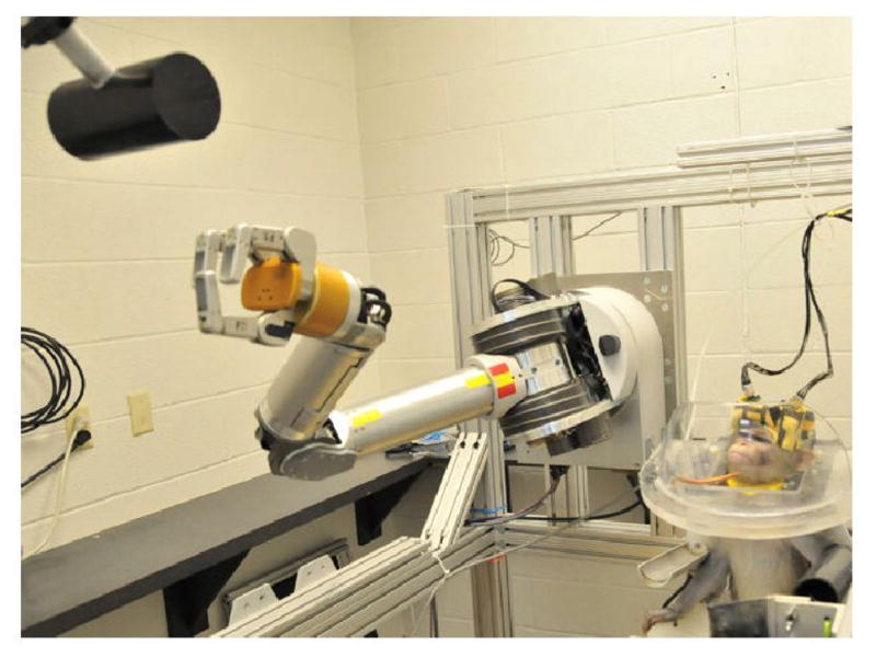
7-DoF brain-machine interface experiment [5].
Shared control is a concept originating in telerobotic and robotic surgery applications in which operator control of a robot is modified to keep robot movements within safe boundaries or enhance task performance [7], [8]. A kind of shared control system called the “Virtual Fixture” (VF) was introduced by Rosenburg [9] to describe the concept of embedded guidance or constraint within human-machine interactive systems. In systems that use virtual fixturing, a user controls the general movement of an effector robot but the virtual fixturing algorithm modulates that movement to enhance task performance. These algorithms guide the robot endpoint towards or away from specified areas of a workspace [10]–[12].
Shared control has been applied to task training in general for human-operated robots, where user-controlled robot movements are corrected towards goal trajectories as humans learn to control devices independently [13], [14]. The concept of shared control in brain-computer interfaces has been employed for manipulator stabilization [15], for cooperative task completion using reinforcement learning [16], for actuating coordinated robotic hand postures [17], and for assisting in control of an EEG-guided wheelchair [18]. In previous BMI work in our laboratory, the related concept of “deviation gain” was applied to 4-DoF control [3].
In this paper we present a new method for shared-control guidance. This method of “Positive-Span” Virtual Fixturing extends the concept of Virtual Fixtures to guide both translational and rotational DoF of a brain-controlled robot hand toward whole sets of robot poses that would allow an object to be grasped. This system was used to successfully train monkeys to operate the 7-DoF BMI [5], leading directly to the simplified system of “ortho-impedance” used to guide human subject BMI control in a similar experiment [6].
The specific advantages of the Positive-Span Virtual Fixturing method include
Extension of Virtual Fixtures to coordinated motion in high-dimensional control spaces, e.g. to include control of both manipulator translation and rotation.
Motion towards or along irregular fixture shapes or clouds of points that can be used directly in the positive-span VF control law, without decomposition of constraint surfaces to lines or planes.
The underlying motivation for the creation of the Positive-Span Virtual Fixturing method comes from the desire to move towards integration of BMI- or otherwise user-controlled robotic systems with automated grasp or movement planning systems. These hybrid systems could be used for training or to enhance overall system performance in high-dimensional control applications. Grasp planning systems commonly produce an n-dimensional point set representing individual poses within the manifold of poses that would effectively grasp an object. The Positive-Span Virtual Fixturing system is compatible with direct constraint of robot movement towards these n-D point sets or manifolds.
II. Positive-Span Virtual Fixture Control Law
In a well-known formulation for Virtual Fixturing [10], a control law is described that constrains the admittance of a human-controlled system in directions defined instantaneously by a line or plane. The control law was applied as a “virtual contact” that governs an anisotropic admittance for a system that transduces human input force (f) to robot output velocity (v). The virtual fixture equation
| (1) |
decomposes input into its projection to a line or plane representing the “preferred directions” of an input fixture (fδ = Dδf), and its residual fτ = f − fδ, where Dδ is the projection operator over the input fixture set δ, s.t. Dδ = δ (δT δ)−1δT. In this formulation, δ contains a 3 × m, 0 < m < 3 time-varying matrix with column rank corresponding to a 1-D or 2-D orthonormal basis for a line or plane fixture. Output projections of input vectors to the line or plane defined by δ were governed by the admittance c, while orthogonal movements were additionally attenuated by cτ.
We propose a related control law to generalize fixtures over complex shapes in n-dimensional control space. Consider the corresponding control law (c omitted)
| (2) |
which is identical to the control law above except that the projection of the n × 1 input ϕ is over the “positive span” of the fixture vector set δ*. The positive span as defined by Mason [21] is pos({zi}) = {Σkizi|ki ≥ 0} for a set of vectors {zi}, in this case the subspace of the input reachable by the basis vectors in δ* applied with positive multiplicative coefficients only, δ* is an n × m matrix of any number of constraints m in any number of dimensions n. The remaining control equations are
| (3) |
| (4) |
| (5) |
where Δ represents a selection of vectors from δ* that positively span the input command vector ϕ. DΔ is a projection operator onto these positively spanning vectors Δ. No rank restrictions are imposed on δ* and thus Δ. This new control law has the effect of preserving the portion of input directed toward the polytope described by δ* while attenuating its orthogonal component. Instead of constraining movement toward a 1-d or 2-d subspace, movement toward irregular fixture geometry in 3 dimensions or more can now be embedded within the VF control law.
As this algorithm relies on the projection of the input to some set of basis vectors Δ, the basic stability arguments presented in [10] apply to the fixturing system here, while noting that in high-dimensional control spaces input in one domain or type of movement (e.g. translational velocity) can result in projection to output in another domain (e.g. rotational velocity). If not desired, individual columns can take values only over dimensions in which coordinated motion is desired (for example see Section III-A).
A. Positive Span Vector Determination
The modified VF control law does not specify a particular projection of the input to the positive span of the δ* matrix. One formulation for a closest-point projection of ϕ to the fixture vectors is to the surface of the n-dimensional convex cone bounded by the columns of δ*. This is a quadratic programming problem to maximize the magnitude of the projection of ϕ to the δ* vectors in
where λ is a diagonal matrix of coefficients corresponding to each column vector in δ*. When ϕ is outside of the convex cone formed by the columns of δ* this can be performed by taking the convex hull of the origin and extended points on the lines indicated by δ, then using a closest-point algorithm to n-D convex hulls such as GJK [22]. Because of the poor performance of convex hull algorithms beyond the third dimension, a different projection to the positive span was used here in which a “greedy” set of fixture vectors for inclusion in Δ were selected in turn to each maximally project onto the input. The algorithm to determine these vectors is similar to Gram-Schmidt orthonormalization except that each basis vector is chosen for its individual maximal projection on ϕ. The first two basis vectors are chosen as
| (6) |
| (7) |
| (8) |
| (9) |
| (10) |
| (11) |
where colmaxδ(y) returns the column of matrix δ on which y projects maximally. Numerical subscripts refer to matrix columns. The algorithm terminates when the maximum projection of ϕ′…″ on any column in ϕ*′…″ ≤ 0.
Simple illustrative examples of selecting fixture vectors δ* include movement toward a region of arbitrary shape and movement along a path. As an example of movement toward a shape, Fig. 2 (left) shows some translational δ vectors directed at the vertices of a cube-shaped spatial target. For rotations, angular velocity vectors in δ can be generated as infinitesimal rotations from the current manipulator orientation leading towards target orientations. For any type of control space, if the robot is located on the interior of a target region, it will move freely if fixture vertices are included in δ to span control dimensions, as shown in Fig. 2 (right). The system will behave similarly for movement towards or inside more complex shapes or point clouds requiring more δ vectors to define (see examples in Results).
Fig. 2.
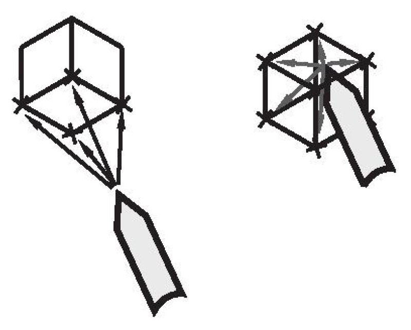
Illustration of a 4-column δ* matrix directing motion towards a cube (vectors on interior of convex cone not shown).
To place a fixture that constrains a robotic manipulator toward and along a path, column vectors in δ can be set to point towards the nearest point on the path and points along it in desired directions of translation. The tightness with which the path is followed is dictated by the spread of the basis vectors pointing along the path (Fig. 3). Similar reasoning can be followed to place angular velocity constraint vectors toward more closely or widely spread rotations on a path of desired orientations. Combinations of region pursuit and path following can be performed by choosing δ* vectors pointing to selected local regions of target geometry.
Fig. 3.

(Left) Tight bidirectional path-following with vectors pointed at closely-spaced points on the path, (Center) vectors through the same points on the path guide the robot when the manipulator leaves the path, and (Right) more forgiving path following with more widely-spaced δ* vectors.
III. Results
A. On-Line Virtual Fixturing Experiment
An experiment was devised in which the performance of the modified VF system was tested for online robot control assistance in a grasping task. The shared control and robotic systems used in this experiment were identical to that in the BMI experiments reported in [5], but the control input was provided by human subjects using hand-held controllers rather than a brain-machine interface. The purpose of this experiment was to prototype the fixturing system to be used for BMI training and verify that the modified VF system was able to adjustably aid subjects in real time as designed. Experimental trials were approved by the Institutional Review Boards at the University of Pittsburgh and Carnegie Mellon University.
In this experiment, a Barrett WAM robotic arm (Barrett Technologies, Cambridge, Mass., USA) was mounted across from a DENSO (DENSO Robotics, Long Beach, CA, USA) industrial 6-DoF arm (Fig. 4) with a cylindrical grasp target attached to it. Subjects stood in the room with the robots and controlled the WAM using a handheld game controller (Sony Six-axis Controller, Sony Corporation, NY, NY). Four degrees of freedom were input through the movement of two thumb-controlled joysticks, and an additional 2 input DoF were provided by two sets of pressure-sensitive trigger buttons. The control space of the robot was the set of 3-D linear and 3-D angular velocities centered at the palm of a Barrett Hand (Barrett Technologies) mounted at the end of the WAM, with no control over the fingers in this experiment. Each input DoF was mapped to a movement DoF that spanned either the 3 linear or 3 rotational degrees of freedom at the palm, so that for instance movement of one of the sticks upward would move the robot toward a corner of the workspace, movement of the other stick left would move it towards an orthogonal corner, and pushing one of the buttons would rotate the robot endpoint in the direction of the “corner” of angular velocities with a simultaneous yawing, pitching, and rolling movement.
Fig. 4.

(Left) A view of the robotic setup in the human subject task, (Right) A schematic of the setup in the room including the human subject.
At the beginning of each experimental trial, one of 30 combinations of linear and rotational targets was selected and the robots moved to corresponding starting positions. A target region was defined as the WAM robot reaching within 12 cm and 40 total degrees of orientation from being directly in front of the target cylinder*.
As each trial began, subject movement commands input from the controller were sampled at 30 ms intervals, filtered by the Positive-Span Fixturing algorithm, and passed to the robot. Commanded WAM velocities output by the positive span VF system were achieved by the WAM using PID control implemented in custom low-level control software. Each trial would register as a failure after 5–7 seconds† unless the WAM endpoint entered the target region during this time. At each 30 ms interval, vectors in the δ* matrix were generated pointing from the current robot pose to the linear and rotational target boundary points generated at the beginning of the trial. Linear and rotational examples of this are shown in Fig. 5. Here, each column embedded either linear or rotational constraints but not both, i.e. , where columns in and columns in such that subjects could move in ranges of linear and rotational DoF without forcing the manipulator toward individual 6-D grasps (see Section III-C where coordinated 6-D poses were used).
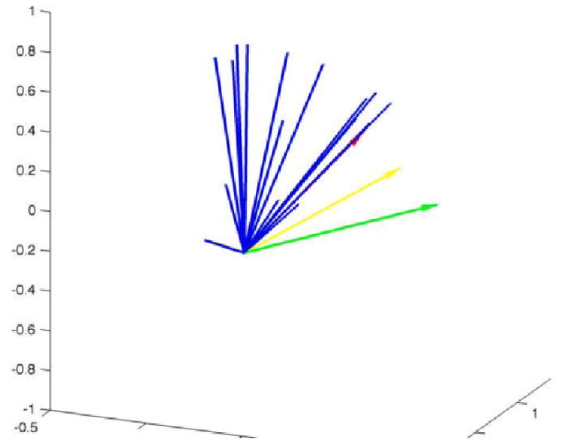
Fig. 5.
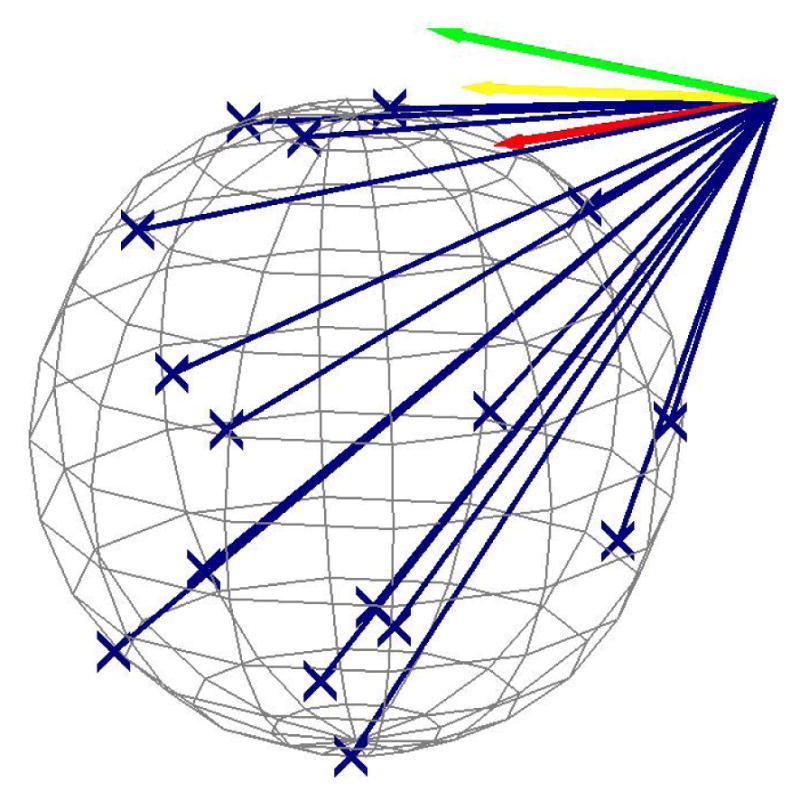
Translation target set with δ* vectors. Vectors show positive span VF output from single input for cτ = {1.0, 0.5, 0} in {green, yellow, red}.
Nine subjects who had not previously controlled the robot each performed 80 experimental trials with the Positive Span Virtual Fixturing-enabled robot control system. cτ values for all 6 dimensions were initially set to 0.2 such that 80% of control error was attenuated. During the first 60 trials, cτ values were increased at a constant rate per trial until the robot was fully controlled by each subject starting on the 61st trial. An example of how the Positive Span Virtual Fixturing method could affect trajectories over a whole trial when applied with different levels of cτ is shown in Fig. 7.
Fig. 7.

Translational trajectory for cτ = {1,0.5,0} in {green, yellow, red} given identical whole-trial input recorded from the experiment.
Subject performance was measured using the average deviation from direct movement from the starting position to the target. Rotational deviation from the closest path to target was calculated using the Slerp algorithm [23]. The relationship between error attenuation coefficients cτ and control error are indicated in Fig. 8 and 9. Subjectively, users felt that smaller amounts of shared-control assistance (cτ = 0.8) helped to keep the system under control while learning the task, especially for rotational DoF. Higher amounts of shared control (cτ < 0.5) were felt by subjects to be too restrictive and not allow subjects to explore the control space, even if success rates were higher. These results influenced the policy regarding adjustment of shared control parameters during the monkey BMI experiments (see below).
Fig. 8.

Error attenuation level cτ vs. mean trial translational error. Points (x) show performance averaged over trials for each subject at different assistance levels, and average over subjects as bars. Improvements in individual performance vs. no assistance are significant at p < 0.05 for 0/10 subjects with low assistance, 5/10 subjects with medium assistance, and 10/10 with high assistance.
Fig. 9.

Error attenuation level cτ vs rotational error. Differences in performance from no assistance are significant at p < 0.05 for 1/10 subjects with low assistance, 4/10 with medium assistance, and 7/10 with high assistance.
B. On-Line Brain-Machine Interface Experimentation
In the 7-DoF monkey BMI experiment, the modified VF system used in the online human control experiment was applied to monkeys learning to control the device using a BMI. Instead of control commands originating with a handheld controller, the activity of neurons was directly recorded and output as 6-DoF motion commands that were fed directly into the modified VF system during training. Due to the difficulty of training monkeys to perform oriented grasping tasks, small cτ values were used during initial control trials in order to allow the monkeys to associate trial completion with a juice reward delivered at the end of each successful trial. As the monkeys began to understand the task goal, the shared control values were adjusted so that success rates were kept high enough (>~ 40%) for the monkeys to maintain attention to the task. Because of the subjective results from the human experiment, cτ was raised to around 0.8 as soon as possible. cτ then remained at 0.8 – 0.95 until monkeys mastered the task. These brain-machine interface results are beyond the scope of this paper and reported in [5]. A simplified version of this system was later used successfully in a human BMI experiment [6].
C. Offline Grasp Pose Manifold Simulation
A simulation was created to show how this type of fixturing can be used for more complex grasping tasks. The Grasplt! grasp planning software system [19], [20] was used to generate a point set of 6-D grasp translation and orientation poses that would allow a virtual Barrett Hand (Barrett Technologies, Cambridge, MA) to be in a form-closure grasp upon flexing the fingers (see [24]). 10000 random 6-DoF simulated user commands were generated in the interval ui = −0.5 … 0.5. To focus the fixturing method to grasp pose orientations on the proximal side of the target object, a heuristic method was used to select the d/3 most proximal target points as the fixturing points, where d is the distance from robot to the closest target point (in cm). The set of 10000 random commands was applied to the robot starting with the pose shown in Fig. 10 using vectors from the current robot position to the heuristically chosen points as VF fixtures for at each time step. Resulting trajectories at different levels of cτ are shown in Fig. 13. The highest cτ at which the hand converged on a target was 0.5 (results shown in Table I). Result poses from the same control inputs at different cτ levels are shown in Fig. 13.
Fig. 10.
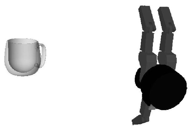
Initial pose in mug grasping simulation with Barrett Hand model.
Fig. 13.

Trajectories of simulated robot for identical command set with cτ set to 0.0, 0.5, 0.7, 1.0 from top left to bottom right. Target orientations are shown for heuristically chosen targets during the last time step.
TABLE I.
Steps to convergence for different levels of cτ, higher levels did not converge in 10000 steps.
| cτ | 0.0 | 0.1 | 0.2 | 0.3 | 0.4 | 0.5 |
| Steps | 3712 | 4210 | 4792 | 5849 | 6788 | 8451 |
IV. Conclusions and Future Work
In this work we present a new control law that generalizes the concept of virtual fixtures to high dimensional control tasks and to irregular fixture shapes. We show results from using this novel VF system in an online control task for simple grasping, then an offline simulation that illustrates its use in a more complex task. The application of our VF system has thus far been in 6 and 7-DoF tasks to be controlled using a brain-machine interface. For control of robots that could perform fine dextrous grasping and manipulation through BMI or any control interface, the VF method described here prototypes the integration of virtual fixturing with real-time grasp planning that includes coordinated finger motions [20]. Its generalization of VF over large numbers of DoF indicates its potential for application to guidance in advanced robotic surgical and telepresence applications [25]. We intend this algorithm to provide a basic framework for extension of shared control to new task domains.
Fig. 6.
Rotational constraint. The target region is difficult to represent, but angular velocity δ* vectors derived from this target space are shown (blue). Positive span VF output from single input are shown for cτ = {1.0,0.5,0} in {green, yellow, red}.
Fig. 11.
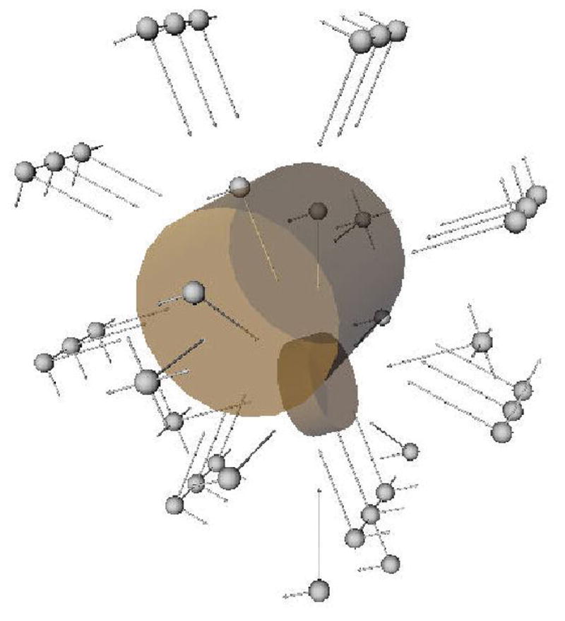
Example initial poses generated by grasp planner. Spheres are at the center of the palm, lines indicate the direction normal to the palm and the direction of the thumb.
Fig. 12.

Form-closure grasps exported from the grasp planner into the Positive-Span Virtual Fixturing system. Orientations chosen by the heuristic mechanism at the first simulation time step are shown.
Fig. 14.

Final grasp output from the planner with cτ = 0.
Acknowledgments
This work was supported by NIH grants NS050256, NS070311, F30N060530, and DARPA grant W911NF-06-1-053.
This work was completed under the advisorship of Andrew Schwartz in his laboratory at the University of Pittsburgh. We would like to thank Yin Zhang for his assistance in data collection.
Footnotes
Target sizes were chosen such that the rotational and translational difficulty were subjectively similar to the experimenters. Rotational targets were generated as random quaternions of 40 degrees of total rotation from the target.
corresponding to primate experiment scheme to minimize “lazy” delayed control strategies.
Contributor Information
Samuel T. Clanton, Rehabilitation Institute of Chicago, Chicago, Illinois.
Robert G. Rasmussen, Department of Bioengineering, University of Pittsburgh
Zohny Zohny, Washington University Department of Neurosurgery, St. Louis, Missouri.
Meel Velliste, Department of Neurobiology and Systems Neuroscience Institute, University of Pittsburgh, Pittsburgh, Pennsylvania.
References
- 1.Serruya MD, Hatsopoulos NG, Paninski L, Fellows MR, Donoghue JP. Instant neural control of a movement signal. Nature. 2002;416(6877):141–142. doi: 10.1038/416141a. [DOI] [PubMed] [Google Scholar]
- 2.Taylor DM, Tillery SIH, Schwartz AB. Direct cortical control of 3D neuroprosthetic devices. Science. 2002;296(5574):1829–1832. doi: 10.1126/science.1070291. [DOI] [PubMed] [Google Scholar]
- 3.Velliste M, Perel S, Spalding MC, Whitford AS, Schwartz AB. Cortical control of a prosthetic arm for self-feeding. Nature. 2008;453(7198):1098–1101. doi: 10.1038/nature06996. [DOI] [PubMed] [Google Scholar]
- 4.Hochberg LR, Bacher D, Jarosiewicz B, Masse NY, Simeral JD, Vogel J, Haddadin S, Liu J, Cash SS, van der Smagt P, Donoghue JP. Reach and grasp by people with tetraplegia using a neurally controlled robotic arm. Nature. 2012;485(7398):372–375. doi: 10.1038/nature11076. [DOI] [PMC free article] [PubMed] [Google Scholar]
- 5.Clanton ST. PhD dissertation. Citeseer: 2011. Brain-Computer Interface Control of an Anthropomorphic Robotic Arm. [Google Scholar]
- 6.Collinger JL, Wodlinger B, Downey JE, Wang W, Tyler-Kabara EC, Weber DJ, McMorland AJ, Velliste M, Boninger ML, Schwartz AB. High-performance neuroprosthetic control by an individual with tetraplegia. The Lancet. 2012 Dec;381(9866):557–564. doi: 10.1016/S0140-6736(12)61816-9. [DOI] [PMC free article] [PubMed] [Google Scholar]
- 7.Khatib O. Real-Time Obstacle Avoidance for Manipulators and Mobile Robots. The international journal of robotics research. 1986;5(1):90–98. [Google Scholar]
- 8.Kumar R, Hager G, Barnes A, Jensen P, Taylor R. An Augmentation System for Fine Manipulation BT – Lecture Notes in Computer Science. In: Delp S, DiGoia A, Jaramaz B, editors. Medical Image Computing and Computer-Assisted Intervention MICCAI 2000. Vol. 1935. Berlin, Heidelberg: Springer Berlin/Heidelberg SN; 2000. pp. CH404–CH404. no. Chapter 99. [Google Scholar]
- 9.Rosenberg LB. IEEE Virtual Reality Annual International Symposium. IEEE; 1993. Proceedings of IEEE Virtual Reality Annual International Symposium; pp. 76–82. [Google Scholar]
- 10.Bettini A, Marayong P, Lang S, Okamura AM, Hager GD. Vision-assisted control for manipulation using virtual fixtures. Robotics, IEEE Transactions on. 2004;20(6):953–966. [Google Scholar]
- 11.Kragic D, Marayong P, Li M, Okamura AM, Hager GD. Human-Machine Collaborative Systems for Microsurgical Applications. The international journal of robotics research. 2005;24(9):731–741. [Google Scholar]
- 12.Abbott J, Marayong P, Okamura A. Haptic Virtual Fixtures for Robot-Assisted Manipulation BT - Springer Tracts in Advanced Robotics. In: Thrun S, Brooks R, Durrant-Whyte H, editors. Robotics Research. Vol. 28. Berlin, Heidelberg: Springer Berlin/Heidelberg SN; 2007. pp. 49–64. no. Chapter 5. [Google Scholar]
- 13.Li Y, Huegel J, Patoglu V, O’Malley M. Progressive shared control for training in virtual environments. EuroHaptics conference, 2009 and Symposium on Haptic Interfaces for Virtual Environment and Teleoperator Systems. World Haptics 2009. Third Joint; 2009. pp. 332–337. [Google Scholar]
- 14.O’Malley M. Progressive haptic and visual guidance for training in a virtual dynamic task. Haptics Symposium. 2010:343–350. [Google Scholar]
- 15.Kim HK, Biggs J, Schloerb W, Carmena M, Lebedev MA, Nicolelis MAL, Srinivasan MA. Continuous shared control for stabilizing reaching and grasping with brain-machine interfaces. Biomedical Engineering, IEEE Transactions on. 2006;(53)(6):1164–1173. doi: 10.1109/TBME.2006.870235. [DOI] [PubMed] [Google Scholar]
- 16.Sanchez JC, Mahmoudi B, DiGiovanna J, Principe JC. Exploiting co-adaptation for the design of symbiotic neuroprosthetic assistants. Neural Networks. 2009;22(3):305–315. doi: 10.1016/j.neunet.2009.03.015. [DOI] [PubMed] [Google Scholar]
- 17.Cipriani C, Zaccone F, Micera S, Carrozza MC. On the Shared Control of an EMG-Controlled Prosthetic Hand: Analysis of User-Prosthesis Interaction. Robotics, IEEE Transactions on. 2008;24(1):170–184. [Google Scholar]
- 18.Perrin X, Chavarriaga R, Colas F, Siegwart R, Millán JdR. Brain-coupled interaction for semi-autonomous navigation of an assistive robot. Robotics And Autonomous Systems. 2010;58(12):1246–1255. [Google Scholar]
- 19.Mller A, Allen P. Grasplt! IEEE Robotics & Automation Magazine. 2004 Dec;11(4):110–122. [Google Scholar]
- 20.Ciocarlie MT, Clanton ST, Spalding MC, Allen PK. Biomimetic grasp planning for cortical control of a robotic hand. Intelligent Robots and Systems, 2008. IROS 2008. IEEE/RSJ International Conference on Intelligent Systems and Robotics; IEEE; 2008. pp. 2271–2276. [Google Scholar]
- 21.Mason MT. Mechanics of Robotic Manipulation. MIT Press; 2001. [Google Scholar]
- 22.Gilbert E, Johnson D, Keerthi S. A fast procedure for computing the distance between complex objects in three-dimensional space. IEEE Journal on Robotics and Automation. 1988 Apr;4(2):193–203. [Google Scholar]
- 23.Shoemake K. SIGGRAPH ’85. New York, NY, USA: ACM; 1985. Animating rotation with quaternion curves; pp. 245–254. [Google Scholar]
- 24.Mller A, Knoop S, Christensen H, Allen P. Automatic grasp planning using shape primitives. 2003 IEEE International Conference on Robotics and Automation (Cat. No.03CH37422); 2003. pp. 1824–1829. [Google Scholar]
- 25.Ryden F, Chizeck HJ. Forbidden-region virtual fixtures from streaming point clouds: Remotely touching and protecting a beating heart. 2012 IEEE/RSJ International Conference on Intelligent Robots and Systems; Oct. 2012; IEEE; pp. 3308–3313. [Google Scholar]