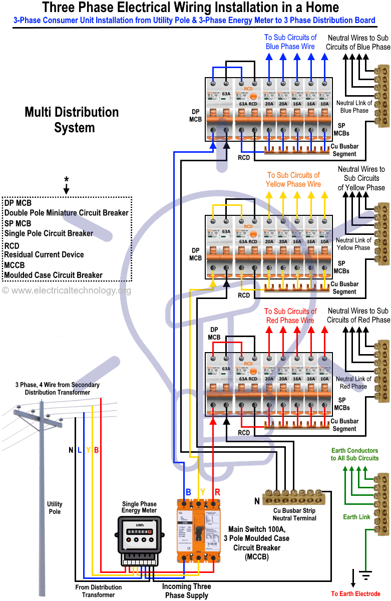
3 Phase 208V Wiring Diagram Collection.
Avoid shortages and malfunctions when electrical wiring your car's electronic devices. Before you start any DIY electrical wiring project, it’s crucial that you have the right ingenuity, as well as the right tools and materials for the job.
3 Phase 208V Wiring Diagram

Essential Tips for Secure Electrical Repairs
1. Test for Strength
The best approach to prevent power shock would be to USUALLY test wires plus devices for strength before taking care of all of them or near all of them. Simply shutting away the power isn't very good enough.
Additional, it's not uncommon with regard to circuit breaker containers to become mislabeled, especially if the electrical support have been extended or perhaps adapted over typically the years. The circuit breaker label may well not accurately describe the particular circuit breaker really controls.
Always analyze for power just before working on any kind of circuit wires.
2. Check Amperage Scores
All electrical cabling and devices have got an amperage, or perhaps amp, rating. This is the optimum amount of electrical present they might safely carry. Most traditional household circuits are rated regarding 15 amps or 20 amps, while large-appliance circuits (such as for electric dryers and ranges) might be rated with regard to 30, 40, 55 amps, or even more.
Whenever installing or exchanging wiring or devices, all of typically the parts you utilize should have the appropriate amperage rating with regard to the circuit. With regard to example, a 20-amp circuit must have got 12-gauge wiring, which usually is rated regarding 20 amps. In case you install 14-gauge, 15-amp wiring on that circuit, a person create a fireplace hazard because the 20-amp circuit breaker safeguarding that circuit may not shut down just before the 15-amp wiring overheats.
Choosing typically the Right Amperage
Any time replacing a change, light fixture, or even outlet receptacle, make sure not to be able to use a device of which is rated for more amperage compared to the circuit carries. This is especially important when exchanging receptacles. A container rated for 20-amps has a distinctive prong condition inside which among the vertical slots contains a T shape. This condition allows 20-amp devices, which have an identical T-shaped prong, to become inserted. Installing such a receptacle on a 15-amp circuit makes it possible to possibly overload the particular circuit if an individual plug this type of 20-amp appliance into it.
Take note, however, there is zero danger to putting in 15-amp receptacles inside 20-amp circuits since it is completely fine when the plug-in device draws less power as compared to the circuit amperage. In fact, this is very normal regarding 20-amp general-use brake lines to be born with 15-amp receptacles.
3. Make Restricted Wiring Connections
Electrical energy travels along conductors, like wires plus the metal connections of outlets plus sockets. Tight connections between conductors generate smooth transitions coming from one conductor to a new. But loose connections act like rate bumps, restricting the particular flow and producing friction and heat. Very loose connections can cause arcing, by which electricity gets through the air through one conductor in order to another, creating incredible heat.
Prevent open fire hazards by generating sure all cabling connections are restricted and also have full contact from the conductors being joined. When splicing wires together, constantly use approved cable connectors ("wire nuts").
Outlet receptacles and switches tend to be manufactured with push-fit wire connection slots on the back, together with the traditional screw-terminal connections on the attributes from the device. These types of push-fit connections are usually notorious for dislodging or failing, therefore professional electricians almost unanimously avoid these people in favor associated with making very limited and secure attach terminal connections.
4. Respect Grounding plus Polarization
Grounding plus polarization are important for the safety regarding modern electrical methods. Grounding provides a risk-free path for run away electrical current caused by a fault or other problem in a circuit. Polarization helps to ensure that electrical current travels from the source together "hot" wires plus returns to the particular source along natural wires.
Always follow manufacturer's wiring blueprints when replacing a fixture, and understand—and use—your home's grounding system to guarantee grounding and polarization remain intact.
Presently there are a variety of approaches to test for grounding plus polarization. A simple plug-in circuit analyzer application, available for a few dollars, will create it possible in order to routinely check shops to be sure they usually are wired correctly.
5. Box and Clamp It
The National Electrical Code (NEC) requires that all electrical wiring connections be produced within an appropriate enclosure. In most instances, this means an electrical box. Enclosures not only protect the connections—and protect people from accidental contact together with those connections—they furthermore provide means for securing conductors (like power cables) and gadgets.
The rule here is simple: don't be lazy. If you need to create a wiring splice, use a junction box in addition to secure the cables to the package with cable clamps. Never leave the splice or some other connection exposed or perhaps unsecured.
