A hall effect sensor pinout is a component renowned for its usefulness in detecting magnetic objects. However, this is not the only primary use of this sensor, as you'll find out from this article. We'll cover the hall effect sensor pinout, working principle, where to use it, and its wide range of applications. Hence, for further info, check out our detailed guide.
Contents
- What is a Magnetic Hall Effect Sensor?
- A3144 Hall Effect Sensor Pin Configuration
- A3144 Hall Effect Sensor Specifications
- Working Principle of A3144 Hall Effect Sensor
- Where to Use the Hall-effect Sensor
- How to Use the Hall-effect Sensor
- Alternative Digital Hall-effect Sensors
- Other Analog Hall-effect Sensors
- A3144 Hall Effect Sensor Applications
- 4 Pin Hall Effect Sensor Pinout: A3144 Hall Effect Sensor Module
- A3144 Hall Effect Sensor Module Characteristics
- How to Build a Hall Effect Sensor Circuit with Arduino
- Components Required
- Key Steps
- Summary
What is a Magnetic Hall Effect Sensor?
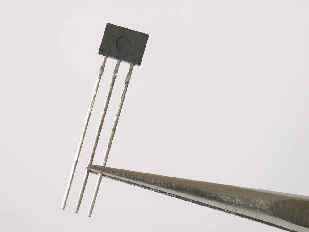
Magnetic field sensor
It is a non-latching integrated sensor that is primarily handy in magnet pole polarity identification. During use, one side of the Hall effect sensor module identifies the positive magnetic pole while the other identifies the negative pole.
In the market, you'll come across two sorts of Hall-effect sensors. One is a digital output hall sensor, while the other features an analog output. Here, we're interested in the A3144 Hall Effect Sensor, which delivers a digital output.
A3144 Hall Effect Sensor Pin Configuration
This digital output hall sensor has three main pins, namely:
- VCC (Power Pin)- It is the power supply input pin (+5V).
- Ground Pin- It is essential in connecting the circuit to the ground.
- Digital Output Pin- The pin outputs a high whenever there's a magnetic field in the surrounding. Also, its output voltage equals the operating voltage.
A3144 Hall Effect Sensor Specifications
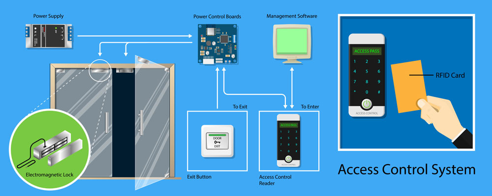
Hall effect sensors are useful in magnetic door systems.
- It is a digital output Hall-effect sensor with an operating voltage of 4.5V to 28V.
- Secondly, its output current is 25mA, and it can detect magnetic polarities (North and South poles).
- It also features a turn-on and turn-off time of 2uS and has an operating temperature of between 40°C and 85°C.
- In addition, its operating voltage equals the output voltage, and the module has a reverse polarity protection feature.
- Compared to the analog input hall effect sensor, this module is smaller, frugal in power consumption, and easy to interface with microcontrollers.
- Lastly, it is essential in industrial and automotive applications.
Working Principle of A3144 Hall Effect Sensor
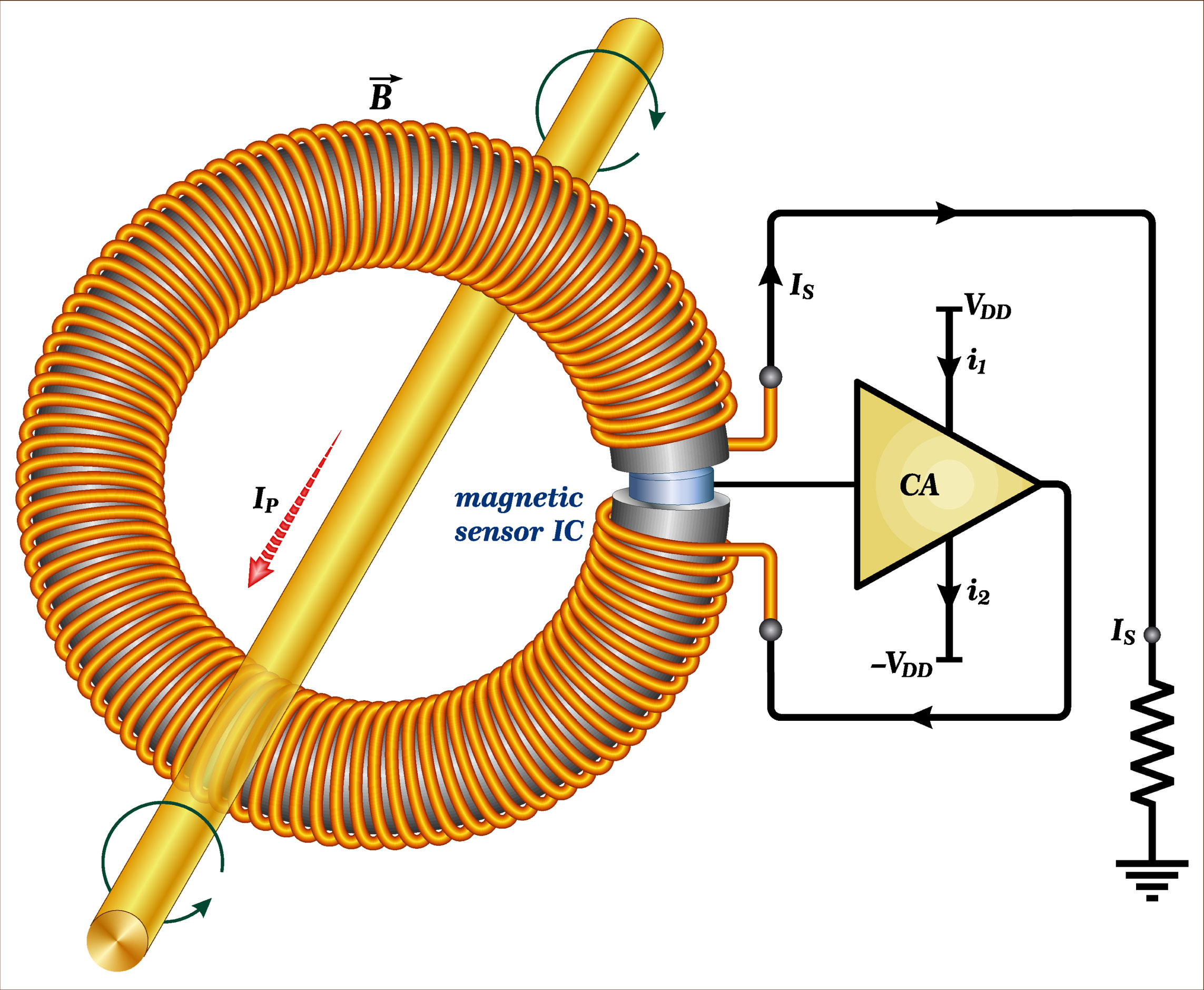
A hall effect current sensor transformer system
All Hall Effect Sensors have one material capable of producing a magnetic field. But, the charge of the magnetic field is in an inactive form. Thus, applying a voltage to these hall devices activates the charges.
Similarly, passing a beam of charged particles through the magnetic field prompts its reflection to a straight path. The second beam acts as a current-carrying conductor. Thus, in principle, we now have two beams, one carrying the magnetic field and the other as a current-carrying conductor.
Consequently, the plane formed by the first beam has a positive charge while the second plane has a negative charge. The voltage between the two planes is the Hall effect/ hall voltage.
Lastly, suppose the forces of the two planes are similar, and the separation ceases. At such a point, there's no current change; thus, the hall voltages will give the flux density of the system.
Where to Use the Hall-effect Sensor
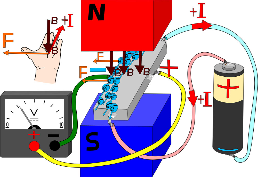
Illustrating how magnetic detection occurs
An A3144 Hall Effect Sensor functions via the hall effect principle; hence it helps detect magnets. Also, each side of the hall effect sensor digital module can identify one pole. One side detects the north pole while the other identifies the south pole.
Among the critical applications of a hall effect sensor digital module is interfacing with a microcontroller. Primarily, this is because the hall sensor module operates on the transistor logic.
Other uses include detection of the presence of a magnet and speed measurement of a moving object.
Special Offer: Get $100 off your order!
Email [email protected] to get started!
How to Use the Hall-effect Sensor
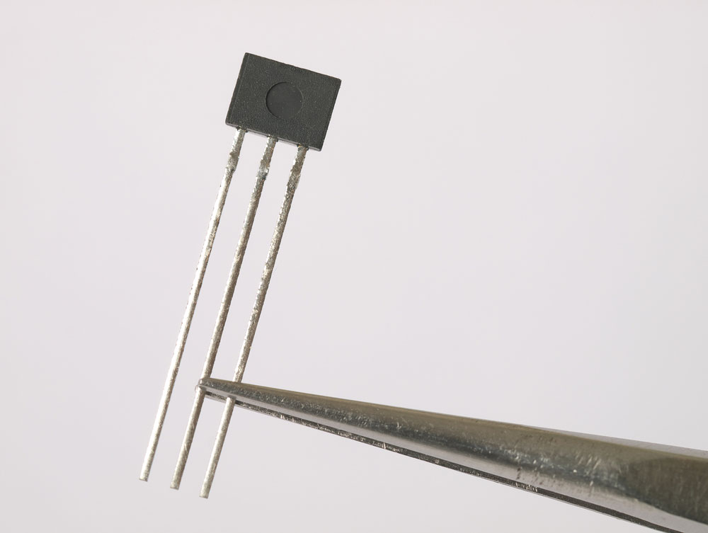
A 3-pin Magnetic Field Sensor
Earlier, we mentioned that there are two kinds of hall effect sensor modules. One gives an analog output, while the other integrated hall effect non-latching sensor gives a digital output.
From the a3144 hall sensor specifications and features we've covered, it is apparent that it's a digital sensor. Thus, its output is at a low upon detecting a magnet. Otherwise, the output is high in the absence of a magnet.
Therefore, the circuit must include a pull-up resistor to ensure that the output remains high during the previous state. Also, it's essential to have a capacitor that will filter the noise that can infiltrate the digital output.
Alternative Digital Hall-effect Sensors
- OH090U
- A3143
- US1881
- A3141
- A3142
Other Analog Hall-effect Sensors
- A1301
- A1302 Hall effect
- ASC712
- SS495B
A3144 Hall Effect Sensor Applications

An electronic speed detector system
- The sensors are helpful in the identification of magnetic objects in automation systems.
- Also, the robust presence sensor is handy in magnetic pole identification in BLDC motors.
- Thirdly, they are useful in measuring automobile speed and handy in magnetic door systems.
- Also, they’re useful in magnetometers.
4 Pin Hall Effect Sensor Pinout: A3144 Hall Effect Sensor Module
Earlier, we covered an A3144 with three pins. However, there's also a hall effect sensor module with four pins whose functions are as follows.
- VCC- It's the Power supply pin.
- GND Pin- The terminal via which you connect the sensor to the ground.
- DO/ Digital Output Pin- It's the one that connects to the microcontroller's digital terminal.
- AO/ Analog Output Pin- The pin is similar to the DO, but this one outputs analog signals. Thus, it connects to the microcontroller's analog pin.
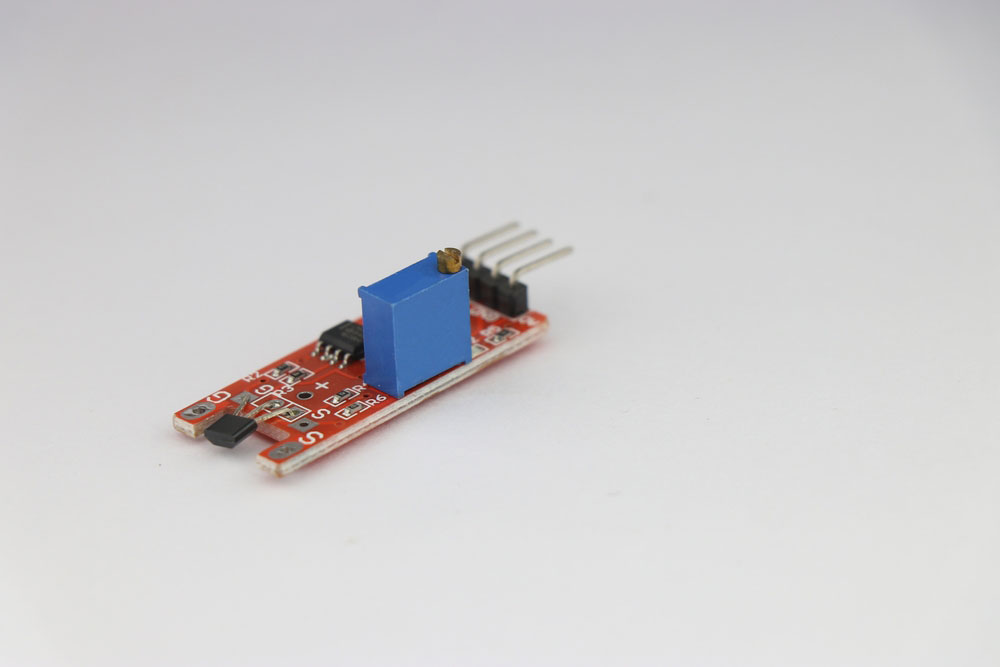
Linear hall effect sensor module for Arduino and other microcontroller board projects
A3144 Hall Effect Sensor Module Characteristics
This module is made of the following components:
LM393 IC
This IC acts as the Hall sensor’s voltage comparator. During use, the IC compares the preset’s threshold voltage to that of the Hall effect’s sensor terminal.
Hall Effect Sensor
It has magnetic sensing properties and among its key features is relatively enhanced sensitivity stability to temperature variations. Also, it can detect an extensive range of negative and positive magnetic fields.
Preset or Trimmer pot
As the name suggests, the Trimmer Pot is imperative in adjusting the digital output’s sensitivity.
Other essential components of the module include resistors, status LED, power, and a capacitor.
How to Build a Hall Effect Sensor Circuit with Arduino
Our project entails an elaboration on how to build a hall effect sensor circuit. Our circuit aims to detect the presence of magnets in the vicinity of the circuit. Also, remember that you can use different kinds of Hall sensor modules for this project. But in our case, we'll use the Allegro A1302 hall effect sensor.
Components Required
A USB Connector
An A1302 Hall Effect Sensor or any other alternative sensor
Key Steps
- Connect the sensor module to the Arduino, as shown in the diagram below.
- Note that the connector's side B will connect to Arduino while the other end will connect to the computer. This connection ensures the Arduino IDE interprets the IC's voltage output.
- Next, run the code below into the IDE.
- Then, once it is working properly, place a magnet in the vicinity of the circuit. The computer will then give a magnetic field reading of the simple circuit.
Summary
Using the above explanation on the working of this module, you can easily identify the presence of a magnet, among other essential applications. Besides, for your project, you can opt for the alternative hall sensors we've listed above. If you have a question, don't hesitate to contact us. We're ready to assist you at all times.
Special Offer: Get $100 off your order!
Email [email protected] to get started!


