LTE Architecture and interfaces
51 likes30,238 views
This document provides an overview of LTE architecture and interfaces. It begins with a brief history of 3GPP and IEEE standards evolutions leading to LTE. It then discusses the key capabilities and performance targets of LTE such as higher data rates, lower latency, and improved spectrum efficiency. The document outlines the LTE system architecture including the Evolved UTRAN and Evolved Packet Core. It describes the network interfaces between these components and other 3GPP networks for interworking and roaming. In summary, the document covers the evolution and standardization history driving LTE, its important technical capabilities, and high-level network architecture.
1 of 53
Downloaded 2,315 times


















Recommended
LTE - Long Term Evolution


LTE - Long Term EvolutionArief Gunawan The document provides an overview of LTE (Long Term Evolution) network architecture and transmission schemes. It describes the simplified LTE network elements including eNB, MME, S-GW and P-GW. It explains the downlink transmission scheme using OFDMA and reference signal structure. It also covers uplink transmission using SC-FDMA, control and data channels as well as frame structure in both FDD and TDD modes.
Throughput calculation for LTE TDD and FDD systems


Throughput calculation for LTE TDD and FDD systemsPei-Che Chang This document discusses the calculation of throughput for LTE TDD and FDD systems. It explains that LTE systems have configurable channel bandwidth and modulation schemes, unlike fixed CDMA systems. The document then provides an example calculation of throughput for a 20 MHz bandwidth LTE FDD system using 100 resource blocks, 64QAM modulation, and 4x4 MIMO. It calculates the downlink throughput as approximately 300 Mbps and uplink as 75 Mbps after accounting for overhead. Similar calculations are shown for LTE TDD systems using different frame configurations.
LTE Call Processing and Handover


LTE Call Processing and HandoverSitha Sok •CPS (Call Processing Software): LTE Control & Bearer Protocol processing
•OAM (Operation and Maintenance): eNB Operation and Maintenance
•MW (Middleware): IPC and Redundancy function
•IPRS (IP Routing Software): Routing protocol operation
•NP SW (Network Processor Software): Packet forwarding function
•OS (Operating System): Embedded Linux
•DD (Device Driver): initializing and setting the devices
LTE (Long Term Evolution) Introduction


LTE (Long Term Evolution) IntroductionGuisun Han This slide for your understanding on LTE !
LTE, the wireless access protocol for 4G mobile network service, has evolved from GSM and WCDMA based on 3GPP!
The contents of this slide is below;
I. LTE Introduction
II. LTE Protocol Layer
III. SAE Architecture
IV. NAS(Non Access Stratum) Protocols
V. EPC Protocol Stacks
With my regards,
Guisun Han
2 g data call flow


2 g data call flowAlfred Ongere The document discusses GPRS network architecture and processes. It describes how a mobile station (MS) attaches to and detaches from the GPRS network by communicating with the SGSN and HLR. It also describes how a temporary block flow (TBF) is established to enable data transfer between the MS and network. Additionally, it outlines how a packet data protocol (PDP) context is activated and deactivated to manage the subscriber's data session.
LTE Basic


LTE Basicneerav_adhikari LTE (Long Term Evolution) is a 4G wireless technology designed to support higher data speeds and capacities. It uses OFDMA for the downlink and SC-FDMA for the uplink. LTE supports MIMO to increase data rates through multiple antennas. The LTE network architecture consists of the eNodeB base stations, Mobility Management Entity (MME) for control plane functions, Serving Gateway (SGW) for user plane functions, and Packet Data Network Gateway (PGW) connecting to external networks. Voice can be supported in LTE through Circuit Switched Fallback (CSFB) to legacy networks or using Voice over LTE (VoLTE) with IP Multimedia Subsystem (IMS
LTE optimization


LTE optimizationجامعة تعز كلية الهندسة وتقنية المعلومات Taiz University Engineering This document describes the design of an LTE network optimization project by a group of students from Taiz University. It includes an introduction to LTE, the network planning process, and LTE system architecture. The network planning section discusses coverage planning including link budget calculations and propagation models, as well as capacity planning considering factors like interference levels and supported modulation schemes. The document also provides an overview of LTE system architecture components including the user equipment, E-UTRAN, EPC, and functions of each. It concludes with a section on LTE radio frequency optimization methods.
Introduction to LTE


Introduction to LTENadisanka Rupasinghe This document provides an overview of 4G LTE technology. It discusses key LTE concepts such as OFDM and MIMO used in the downlink and uplink, as well as requirements for IMT-Advanced systems. It describes the 3GPP releases that specified LTE and LTE-Advanced standards and components of the LTE network architecture including the E-UTRAN, EPC, and interfaces between nodes. The document also provides explanations of OFDM, MIMO, SC-FDMA, and the LTE physical layer frame structure and resource grid. Special features introduced in LTE-Advanced like carrier aggregation and relaying are also summarized.
259711021-LTE-Training.pptx


259711021-LTE-Training.pptxssuser6f5356 The document provides an overview of LTE and LTE optimization. It discusses the LTE architecture including the Evolved Packet System components like eNodeB, MME, S-GW, P-GW, HSS, and PCRF. It describes the LTE air interface including bandwidths, frequency bands, and UE capabilities. It also covers call flows, handovers, and optimization topics like network optimization processes, RF optimization objects, and troubleshooting metrics.
Umts call-flows


Umts call-flowssivakumar D This document provides an overview of the network architecture and signalling protocols in UMTS networks. It describes the main network elements of UTRAN, UE and CN. It explains the interfaces between these elements and the protocols used for communication, including RRC for UE-RNC signalling, RANAP for RNC-CN signalling, and NAS protocols for non-access signalling between UE and CN. It also summarizes the protocol stacks used over the Iu interfaces between RNC and CN for circuit-switched and packet-switched domains.
4g interview-question


4g interview-questionManpreet Singh The document contains questions and answers about LTE (Long Term Evolution) technology. LTE aims to improve spectral efficiency, lower costs, and improve services compared to previous standards. It provides peak download rates of at least 100 Mbps and round-trip times of less than 10ms. While LTE is considered a 3.9G technology, LTE Advanced seeks to meet the full ITU 4G requirements including peak rates of up to 1 Gbps for low mobility. The LTE architecture consists of the E-UTRAN access network and EPC core network. Key network elements include eNodeBs, MMEs for mobility management, SGWs for routing and anchoring user data, and PGWs for external connectivity
5G technical_overview_training_sec_1


5G technical_overview_training_sec_1Sajal Kumar Das 5G NR Technical Overview Presentation
Covers the 5G cellular network overview and Technical details
Irat handover basics


Irat handover basicsBamidele Odediya The document discusses Inter-Radio Access Technology (IRAT) handover and cell change, which allows the transition of 3G voice and data services between WCDMA and GSM networks to maintain connections and prevent dropped calls. It describes the IRAT handover evaluation process based on UE measurement reports and covers topics like coverage monitoring, event reporting, parameters, handover sequences, cell change procedures, and directed retry to offload traffic between networks.
Pci planning-for-lte


Pci planning-for-ltechelebix The document discusses the primary and secondary synchronization signals used in LTE networks. It notes that the primary synchronization signal (PSS) and secondary synchronization signal (SSS) are transmitted once every 5 ms on subcarriers in the middle of the frequency band. The PSS is used for detection of carrier frequency and timing, while the SSS identifies the physical cell ID and other parameters. It recommends strategies for assigning physical cell IDs to avoid non-optimal combinations in adjacent cells that could cause long synchronization times and interference.
422738668-LTE-Downlink-Throughput-Optimization-Based-on-Performance-Data [Rep...


422738668-LTE-Downlink-Throughput-Optimization-Based-on-Performance-Data [Rep...SudheeraIndrajith This document provides technical training on optimizing LTE downlink throughput. It discusses:
1. The increasing commercial adoption of LTE networks and rapid growth of LTE users.
2. Challenges in optimizing LTE networks including insufficient analysis capabilities and experience-based adjustments.
3. A proposed optimization scheme involving in-depth analysis of issues like weak coverage, interference and throughput problems to identify root causes and targeted optimization suggestions.
LTE Basic Principle


LTE Basic PrincipleTaiz Telecom Follow us on
YouTube :Taiz Telecom
https://www.youtube.com/channel/UCvtuWqRxx13ELILiQ5uInAQ
Telegram :Taiz Telecom
https://t.me/Taiz_TelecomDevelopment
5G Technology Tutorial


5G Technology TutorialAPNIC This document provides an overview of 5G technology and its advantages over 4G LTE. It discusses the different 5G use cases like enhanced mobile broadband, massive IoT, and critical communications. It describes the evolution of radio technology including the use of new spectrum bands and massive MIMO. It also covers network architecture aspects such as centralized RAN deployments and functional splits between centralized and distributed units. The document is intended as a tutorial for IP engineers to understand 5G network capabilities and requirements.
Throughput Calculation for LTE TDD and FDD System


Throughput Calculation for LTE TDD and FDD SystemSukhvinder Singh Malik In this paper, we discussed about LTE system throughput calculation for both TDD and FDD system.
3GPP LTE technology support both TDD and FDD multiplexing. The paper describes all the factors which affect the throughput like Bandwidth, Modulation, UE category and mulplexing. It also describes how we get throughput 300Mbps in DL and 75Mbps in UL and what are assumptions taken to calculate the same.
Paper describes the steps and formulae to calculate the throughput for FDD system for TDD Config 1 and Config 2.
The throughput calculations shown in this paper is theoretical and limited by the assumptions taken to calculate for calculations
Mobile Networks Overview (2G / 3G / 4G-LTE)


Mobile Networks Overview (2G / 3G / 4G-LTE)Hamidreza Bolhasani Mobile networks have evolved over several generations from 1G analog cellular to 4G LTE networks. This document provides an overview of the fundamental concepts and evolution of mobile networks including discussions of 2G, 3G, 4G networks and the Evolved Packet Core. It describes the core network functions and interfaces as well as basic network scenarios.
01 lte radio_parameters_lte_overview_rl1


01 lte radio_parameters_lte_overview_rl1Md.Akm Sahansha This document provides an overview of LTE functionalities and features. It begins with background on LTE development and standardization. It then describes the LTE network elements and interfaces, including the radio interface between UE and eNB. The document reviews the RRM framework and lists key RRM features, providing status updates on which features are ready in the current release or planned for future releases. It also includes roadmaps showing the planned features and timeline for LTE releases. The document appears to be an internal presentation on LTE technologies and the Nokia Siemens Networks product roadmap.
Introduction to LTE


Introduction to LTESB MN This document provides an overview of Long Term Evolution (LTE) wireless communication technology. It explains that LTE is an evolution of previous GSM/UMTS standards aimed at increasing wireless data network capacity and speed. Key points are:
- LTE uses OFDMA for downlink and SC-FDMA for uplink transmission. It supports flexible bandwidths from 1.4 to 20 MHz.
- LTE has a simplified IP-based network architecture compared to 3G, with reduced latency.
- LTE-Advanced further improves LTE, integrating networks and meeting 4G requirements. It allows for higher data speeds compared to WiMAX and previous LTE.
Core cs overview (1)


Core cs overview (1)Rashid Khan The document provides an overview of Huawei's Core-CS Network and the evolution of WCDMA networks from Release 99 to Release 5. It discusses key aspects of MSC pool networks including improved resource utilization, enhanced network reliability, and reduced signaling traffic. It also covers AOIP and AOTDM, noting that AOIP allows for end-to-end Transcoder Free Operation and uses lower-cost IP networks for transmission on the A interface user plane.
LTE - 3GPP Standard Perspective


LTE - 3GPP Standard PerspectiveMuhannad Aulama The document provides an overview of LTE, including its history within evolving mobile communication standards, the 3GPP standardization process, and key targets and technologies defined for LTE. Some of the major goals for LTE included supporting peak data rates up to 100Mbps downlink and 50Mbps uplink, latency under 5ms, support for bandwidths up to 20MHz, incorporation of multiple antenna technologies, and compatibility with existing standards like UMTS. LTE aimed to substantially improve spectral efficiency and user experience over prior 3G technologies.
Lte default and dedicated bearer / VoLTE


Lte default and dedicated bearer / VoLTEmanish_sapra LTE uses EPS bearers to carry user data traffic. There are two types of EPS bearers - default bearers and dedicated bearers. Default bearers are created for each PDN connection and provide basic "best effort" internet access. Dedicated bearers provide additional tunnels for specific traffic like VoLTE and can have guaranteed bitrates. Dedicated bearers are linked to a default bearer and inherit properties like the PDN address from the default bearer. GTP is the protocol used to encapsulate and carry bearer traffic through the LTE core network.
5G NR radio protocols to support URLLC


5G NR radio protocols to support URLLC3G4G Presented Osman Yilmaz - Team leader, 5G Radio Resource Control, Ericsson at URLLC Conference 2017
** Shared with permission **
Lte system signaling procedures


Lte system signaling procedurestharinduwije The document discusses LTE system signaling procedures. It begins with objectives of understanding LTE architecture, elementary procedures of interfaces like S1, X2 and Uu, and procedures for service setup, release and handover. It then covers topics like system architecture, bearer service architecture, elementary procedures on Uu including connection establishment and release, and procedures on S1 and X2 interfaces. The document aims to help readers understand LTE signaling flows and procedures.
4 g LTE, LTE Advance 


4 g LTE, LTE Advance Sajid Marwat 4G refers to fourth-generation wireless which aims to provide faster data speeds and more capabilities than 3G. 4G LTE and 4G LTE Advanced are competing 4G standards. 4G LTE aims to provide speeds up to 10 times faster than 3G, while 4G LTE Advanced, standardized in 2011, is an enhancement that provides even higher speeds and more advanced technologies. The key difference is that 4G LTE Advanced supports newer technologies for higher performance compared to 4G LTE.
UMTS/LTE/EPC Call Flows for CSFB


UMTS/LTE/EPC Call Flows for CSFBJustin MA (馬嘉昌) It is a handbook of UMTS/LTE/EPC CSFB call flows.
This document is originally edited by Justin MA and it is free to share to everyone who are interested.
All reference/resource are from internet. If there is any copy-right issue, please kindly inform Justin by [email protected].
Thanks for your reading!
Day one 09 november 2012


Day one 09 november 2012Arief Gunawan The document discusses an introduction to LTE presentation given on November 9th, 2012 in Jakarta by Arief Hamdani Gunawan. The presentation covers:
1. An introduction to LTE including the evolution of 3G technologies and the motivation for developing LTE.
2. An overview of the key LTE technologies such as OFDMA, SC-FDMA, and the LTE frequency bands.
3. A discussion of the 3GPP release process and the key features introduced in releases 6-10 such as HSPA, LTE, LTE-Advanced, and carrier aggregation.
3GPP – Long Term Evolution 


3GPP – Long Term Evolution Vishal Pawar 3GPP – Long Term Evolution
Introduction to LTE
LTE Network Architecture
LTE Physical Layer
SC-FDMA
Channel Dependent Scheduling
Cognitive Radio for LTE RRM
Multiple antenna schemes in LTE
LTE-Advanced
Conclusion
Please like and Comments
Mr.Vishal Pawar
MITSOT
www.mitsot.com
www.kmallonline.com
http://telecommunicationsdemystified.blogspot.in/
http://marketingmythsdemystified.blogspot.in/
More Related Content
What's hot (20)
259711021-LTE-Training.pptx


259711021-LTE-Training.pptxssuser6f5356 The document provides an overview of LTE and LTE optimization. It discusses the LTE architecture including the Evolved Packet System components like eNodeB, MME, S-GW, P-GW, HSS, and PCRF. It describes the LTE air interface including bandwidths, frequency bands, and UE capabilities. It also covers call flows, handovers, and optimization topics like network optimization processes, RF optimization objects, and troubleshooting metrics.
Umts call-flows


Umts call-flowssivakumar D This document provides an overview of the network architecture and signalling protocols in UMTS networks. It describes the main network elements of UTRAN, UE and CN. It explains the interfaces between these elements and the protocols used for communication, including RRC for UE-RNC signalling, RANAP for RNC-CN signalling, and NAS protocols for non-access signalling between UE and CN. It also summarizes the protocol stacks used over the Iu interfaces between RNC and CN for circuit-switched and packet-switched domains.
4g interview-question


4g interview-questionManpreet Singh The document contains questions and answers about LTE (Long Term Evolution) technology. LTE aims to improve spectral efficiency, lower costs, and improve services compared to previous standards. It provides peak download rates of at least 100 Mbps and round-trip times of less than 10ms. While LTE is considered a 3.9G technology, LTE Advanced seeks to meet the full ITU 4G requirements including peak rates of up to 1 Gbps for low mobility. The LTE architecture consists of the E-UTRAN access network and EPC core network. Key network elements include eNodeBs, MMEs for mobility management, SGWs for routing and anchoring user data, and PGWs for external connectivity
5G technical_overview_training_sec_1


5G technical_overview_training_sec_1Sajal Kumar Das 5G NR Technical Overview Presentation
Covers the 5G cellular network overview and Technical details
Irat handover basics


Irat handover basicsBamidele Odediya The document discusses Inter-Radio Access Technology (IRAT) handover and cell change, which allows the transition of 3G voice and data services between WCDMA and GSM networks to maintain connections and prevent dropped calls. It describes the IRAT handover evaluation process based on UE measurement reports and covers topics like coverage monitoring, event reporting, parameters, handover sequences, cell change procedures, and directed retry to offload traffic between networks.
Pci planning-for-lte


Pci planning-for-ltechelebix The document discusses the primary and secondary synchronization signals used in LTE networks. It notes that the primary synchronization signal (PSS) and secondary synchronization signal (SSS) are transmitted once every 5 ms on subcarriers in the middle of the frequency band. The PSS is used for detection of carrier frequency and timing, while the SSS identifies the physical cell ID and other parameters. It recommends strategies for assigning physical cell IDs to avoid non-optimal combinations in adjacent cells that could cause long synchronization times and interference.
422738668-LTE-Downlink-Throughput-Optimization-Based-on-Performance-Data [Rep...


422738668-LTE-Downlink-Throughput-Optimization-Based-on-Performance-Data [Rep...SudheeraIndrajith This document provides technical training on optimizing LTE downlink throughput. It discusses:
1. The increasing commercial adoption of LTE networks and rapid growth of LTE users.
2. Challenges in optimizing LTE networks including insufficient analysis capabilities and experience-based adjustments.
3. A proposed optimization scheme involving in-depth analysis of issues like weak coverage, interference and throughput problems to identify root causes and targeted optimization suggestions.
LTE Basic Principle


LTE Basic PrincipleTaiz Telecom Follow us on
YouTube :Taiz Telecom
https://www.youtube.com/channel/UCvtuWqRxx13ELILiQ5uInAQ
Telegram :Taiz Telecom
https://t.me/Taiz_TelecomDevelopment
5G Technology Tutorial


5G Technology TutorialAPNIC This document provides an overview of 5G technology and its advantages over 4G LTE. It discusses the different 5G use cases like enhanced mobile broadband, massive IoT, and critical communications. It describes the evolution of radio technology including the use of new spectrum bands and massive MIMO. It also covers network architecture aspects such as centralized RAN deployments and functional splits between centralized and distributed units. The document is intended as a tutorial for IP engineers to understand 5G network capabilities and requirements.
Throughput Calculation for LTE TDD and FDD System


Throughput Calculation for LTE TDD and FDD SystemSukhvinder Singh Malik In this paper, we discussed about LTE system throughput calculation for both TDD and FDD system.
3GPP LTE technology support both TDD and FDD multiplexing. The paper describes all the factors which affect the throughput like Bandwidth, Modulation, UE category and mulplexing. It also describes how we get throughput 300Mbps in DL and 75Mbps in UL and what are assumptions taken to calculate the same.
Paper describes the steps and formulae to calculate the throughput for FDD system for TDD Config 1 and Config 2.
The throughput calculations shown in this paper is theoretical and limited by the assumptions taken to calculate for calculations
Mobile Networks Overview (2G / 3G / 4G-LTE)


Mobile Networks Overview (2G / 3G / 4G-LTE)Hamidreza Bolhasani Mobile networks have evolved over several generations from 1G analog cellular to 4G LTE networks. This document provides an overview of the fundamental concepts and evolution of mobile networks including discussions of 2G, 3G, 4G networks and the Evolved Packet Core. It describes the core network functions and interfaces as well as basic network scenarios.
01 lte radio_parameters_lte_overview_rl1


01 lte radio_parameters_lte_overview_rl1Md.Akm Sahansha This document provides an overview of LTE functionalities and features. It begins with background on LTE development and standardization. It then describes the LTE network elements and interfaces, including the radio interface between UE and eNB. The document reviews the RRM framework and lists key RRM features, providing status updates on which features are ready in the current release or planned for future releases. It also includes roadmaps showing the planned features and timeline for LTE releases. The document appears to be an internal presentation on LTE technologies and the Nokia Siemens Networks product roadmap.
Introduction to LTE


Introduction to LTESB MN This document provides an overview of Long Term Evolution (LTE) wireless communication technology. It explains that LTE is an evolution of previous GSM/UMTS standards aimed at increasing wireless data network capacity and speed. Key points are:
- LTE uses OFDMA for downlink and SC-FDMA for uplink transmission. It supports flexible bandwidths from 1.4 to 20 MHz.
- LTE has a simplified IP-based network architecture compared to 3G, with reduced latency.
- LTE-Advanced further improves LTE, integrating networks and meeting 4G requirements. It allows for higher data speeds compared to WiMAX and previous LTE.
Core cs overview (1)


Core cs overview (1)Rashid Khan The document provides an overview of Huawei's Core-CS Network and the evolution of WCDMA networks from Release 99 to Release 5. It discusses key aspects of MSC pool networks including improved resource utilization, enhanced network reliability, and reduced signaling traffic. It also covers AOIP and AOTDM, noting that AOIP allows for end-to-end Transcoder Free Operation and uses lower-cost IP networks for transmission on the A interface user plane.
LTE - 3GPP Standard Perspective


LTE - 3GPP Standard PerspectiveMuhannad Aulama The document provides an overview of LTE, including its history within evolving mobile communication standards, the 3GPP standardization process, and key targets and technologies defined for LTE. Some of the major goals for LTE included supporting peak data rates up to 100Mbps downlink and 50Mbps uplink, latency under 5ms, support for bandwidths up to 20MHz, incorporation of multiple antenna technologies, and compatibility with existing standards like UMTS. LTE aimed to substantially improve spectral efficiency and user experience over prior 3G technologies.
Lte default and dedicated bearer / VoLTE


Lte default and dedicated bearer / VoLTEmanish_sapra LTE uses EPS bearers to carry user data traffic. There are two types of EPS bearers - default bearers and dedicated bearers. Default bearers are created for each PDN connection and provide basic "best effort" internet access. Dedicated bearers provide additional tunnels for specific traffic like VoLTE and can have guaranteed bitrates. Dedicated bearers are linked to a default bearer and inherit properties like the PDN address from the default bearer. GTP is the protocol used to encapsulate and carry bearer traffic through the LTE core network.
5G NR radio protocols to support URLLC


5G NR radio protocols to support URLLC3G4G Presented Osman Yilmaz - Team leader, 5G Radio Resource Control, Ericsson at URLLC Conference 2017
** Shared with permission **
Lte system signaling procedures


Lte system signaling procedurestharinduwije The document discusses LTE system signaling procedures. It begins with objectives of understanding LTE architecture, elementary procedures of interfaces like S1, X2 and Uu, and procedures for service setup, release and handover. It then covers topics like system architecture, bearer service architecture, elementary procedures on Uu including connection establishment and release, and procedures on S1 and X2 interfaces. The document aims to help readers understand LTE signaling flows and procedures.
4 g LTE, LTE Advance 


4 g LTE, LTE Advance Sajid Marwat 4G refers to fourth-generation wireless which aims to provide faster data speeds and more capabilities than 3G. 4G LTE and 4G LTE Advanced are competing 4G standards. 4G LTE aims to provide speeds up to 10 times faster than 3G, while 4G LTE Advanced, standardized in 2011, is an enhancement that provides even higher speeds and more advanced technologies. The key difference is that 4G LTE Advanced supports newer technologies for higher performance compared to 4G LTE.
UMTS/LTE/EPC Call Flows for CSFB


UMTS/LTE/EPC Call Flows for CSFBJustin MA (馬嘉昌) It is a handbook of UMTS/LTE/EPC CSFB call flows.
This document is originally edited by Justin MA and it is free to share to everyone who are interested.
All reference/resource are from internet. If there is any copy-right issue, please kindly inform Justin by [email protected].
Thanks for your reading!
Similar to LTE Architecture and interfaces (20)
Day one 09 november 2012


Day one 09 november 2012Arief Gunawan The document discusses an introduction to LTE presentation given on November 9th, 2012 in Jakarta by Arief Hamdani Gunawan. The presentation covers:
1. An introduction to LTE including the evolution of 3G technologies and the motivation for developing LTE.
2. An overview of the key LTE technologies such as OFDMA, SC-FDMA, and the LTE frequency bands.
3. A discussion of the 3GPP release process and the key features introduced in releases 6-10 such as HSPA, LTE, LTE-Advanced, and carrier aggregation.
3GPP – Long Term Evolution 


3GPP – Long Term Evolution Vishal Pawar 3GPP – Long Term Evolution
Introduction to LTE
LTE Network Architecture
LTE Physical Layer
SC-FDMA
Channel Dependent Scheduling
Cognitive Radio for LTE RRM
Multiple antenna schemes in LTE
LTE-Advanced
Conclusion
Please like and Comments
Mr.Vishal Pawar
MITSOT
www.mitsot.com
www.kmallonline.com
http://telecommunicationsdemystified.blogspot.in/
http://marketingmythsdemystified.blogspot.in/
Slides day one


Slides day oneAkhmad Hambali This document provides an overview of LTE technology including:
- The evolution of 3G UMTS networks and the motivation for developing LTE standards.
- Key requirements for LTE such as higher data rates, improved spectrum efficiency, and reduced latency.
- An overview of LTE release versions and their major features such as OFDMA, SC-FDMA, E-UTRAN architecture.
- LTE frequency bands and the expansion of spectrum for 3GPP standards.
- How LTE-Advanced builds upon LTE to meet IMT-Advanced specifications including carrier aggregation and advanced MIMO.
Lte basics


Lte basicsVibhor Gupta The document provides an overview of 3GPP LTE (Long Term Evolution) technology. Key points include:
- LTE is designed to provide high-speed data and media transport with high-capacity voice support through the next decade.
- It enables high-performance mobile broadband services using high bitrates and system throughput in both uplink and downlink with low latency.
- The LTE infrastructure is designed to be simple to deploy and operate across flexible frequency bands from less than 5MHz to 20MHz.
- The LTE-SAE architecture reduces network nodes and supports flexible configurations for high service availability across multiple standards.
Lte training session_1


Lte training session_1Sajal Kumar Das This document outlines an agenda for eight sessions on LTE system overview and operation. Session 1 provides an overview of LTE cellular systems, specifications, and network architecture. Sessions 2-8 cover OFDMA and SCFDMA concepts, LTE transmission schemes, protocol architecture, MIMO, UE operations, cell acquisition procedures, handover, and UE testing. The document lists references on LTE system design books and 3GPP specifications.
3gpp lte


3gpp lteApitan Kongcharoen The document provides a technical overview of 3GPP LTE (Long Term Evolution), including:
1) An overview of cellular wireless system evolution from 1G to 4G, and the standardization bodies 3GPP and 3GPP2.
2) Key technologies enabling LTE such as OFDMA, SC-FDMA, MIMO, and the requirements and specifications of the LTE standard.
3) The network architecture of LTE consisting of the E-UTRAN, EPC, and protocols.
LTE Introduction - Hello World to LTE


LTE Introduction - Hello World to LTESachidananda Sahu Hello World to LTE - It covers basic of LTE and how the telecom technologies evolved in form of generation.
3GPP_4G to 5G networks evolution and releases.pdf


3GPP_4G to 5G networks evolution and releases.pdfXinHuang548256 This document provides an overview of 4G and 5G networks and standards. It discusses the evolution from 3G to 4G networks, including the objectives and key features of LTE networks. It then summarizes the main developments and new features of LTE releases 10 through 13, including the introduction of LTE-M and NB-IoT for IoT connectivity. Finally, it outlines the objectives of 5G networks to support enhanced mobile broadband, massive machine-type communications, and ultra-reliable low latency communications.
Slides dayone-121110052003-phpapp02


Slides dayone-121110052003-phpapp02Engr Kamrul Hasan This document provides an overview of LTE (Long Term Evolution) including its evolution from previous 3GPP standards like UMTS, key drivers and requirements for LTE, LTE technology basics, frequency bands, and features introduced in subsequent releases up to Release 11. It discusses technologies like OFDMA, SC-FDMA and the LTE network protocol. It also outlines the spectrum used for LTE FDD and TDD modes.
High performance browser networking ch7,8


High performance browser networking ch7,8Seung-Bum Lee Presentation material including summary of "High Performance Browser Networking" by Ilya Grigorik. This book includes very good summary of computer network not only for internet browsing but also multimedia streaming.
Wireless communication netwrks.unit 5...3gpp architecture evolution


Wireless communication netwrks.unit 5...3gpp architecture evolutionsangavaisang 1) The document discusses the evolution from GSM networks to multi-access IP networks including 3G, LTE, WiFi and other technologies.
2) A key part of this evolution is the System Architecture Evolution (SAE) which defines an IP-based core network that can support both 3GPP and non-3GPP access technologies in a seamless manner.
3) The IMS (IP Multimedia Subsystem) plays an important role as well, providing all-IP multimedia services across different access networks in a standardized way.
Lte(1)


Lte(1)amirali baha The document discusses the evolution of 3G networks to 4G LTE networks. It describes the key aspects of LTE including the LTE architecture, air interface technologies like OFDMA and SC-FDMA, and the Evolved Packet Core. The goals of LTE were to provide higher data rates, improve spectrum efficiency, reduce latency and simplify the network architecture. LTE adopted an all-IP flat architecture with reduced network elements in the core to help lower costs and complexity.
1 lf-pau-lte


1 lf-pau-ltePankaj Patel Protocol Test Scripting Languages (PYTHON, TTCN), Protocol Testing (Unit Testing, Module Testing, Integration Testing, Conformance Testing),
Protocol Testing Tools
Introduction to 3GPP and LTE standardization


Introduction to 3GPP and LTE standardizationAjin R Nair 3GPP is an organization that develops protocols for mobile telecommunications standards. It established specifications for 3G based on 2G GSM and later developed 4G LTE standards. LTE uses OFDMA for downlink and SC-FDMA for uplink. The LTE network architecture aims to improve scalability by reducing network elements and locating radio protocols in base stations called eNodeBs. 3GPP continues to release new specifications to evolve LTE capabilities towards 5G standards.
LTE @ Yogyakarta, 19 December 2001


LTE @ Yogyakarta, 19 December 2001Arief Gunawan The document provides an overview of LTE (Long Term Evolution) network architecture and technology. It discusses the drivers for LTE including higher data rates and lower latency. It describes the evolution from 3G networks to LTE, which features a simplified all-IP architecture without circuit-switched elements. Key aspects of LTE include OFDMA modulation, support for bandwidths up to 20 MHz, and peak data rates of 100 Mbps downstream and 50 Mbps upstream.
4 g(lte) principle and key technology training and certificate 2


4 g(lte) principle and key technology training and certificate 2Taiz Telecom The document provides an overview of 4G LTE principles and key technologies. It discusses LTE evolution from 3G standards and introduces some of LTE's main features like OFDMA, MIMO and improved spectral efficiency. It describes LTE network elements including eNodeB, MME, SGW, PGW and PCRF. It also covers the LTE air interface and interconnection between network interfaces.
3gpp architecture evolution


3gpp architecture evolutionphilip habib This presentation discusses 3GPP's System Architecture Evolution (SAE) which aims to provide services over any access network through a common IP-based core network. It covers migration from GSM to a multi-access system using SAE/LTE, including support for SIM/USIM/ISIM, security evolution, and interworking of multi-mode terminals and networks through service continuity, multiple registration, and voice call continuity. IMS is also discussed as the service platform for multimedia services in 3GPP networks.
3 gpp – overview


3 gpp – overviewVirendra Uppalwar This presentation is for the people who are interested in mobile release and specifications announced by 3GPP every year, presentation cover all release up to release 12.
Lte By Aziz


Lte By AzizAziz Zoaib The document provides an overview of the 3GPP Long Term Evolution (LTE) cellular network technology. It discusses the goals and key features of LTE, including increased data rates, improved spectral efficiency, scalable bandwidths, OFDM modulation in the downlink, SC-FDMA in the uplink, and multiple antenna techniques. It also describes the LTE network architecture including the Evolved Packet Core and compares LTE to other technologies such as WiMAX.
LTE_and_beyond.pdf LTE (Long-Term Evolution)


LTE_and_beyond.pdf LTE (Long-Term Evolution)luhonijona LTE (Long-Term Evolution) is a fourth-generation (4G) wireless standard that provides increased network capacity and speed for cellphones and other cellular devices compared with third-generation (3G) technology.
LTE is a technology for wireless broadband communication for mobile devices and is used by phone carriers to deliver wireless data to a consumer's phone. Over the previous iteration of 3G, LTE provided high speed, higher efficiency, peak data rates and flexibility in bandwidth and frequency.
LTE offers higher peak data transfer rates than 3G, up to 100 Mbps downstream and 30 Mbps upstream. It provides reduced latency, scalable bandwidth capacity and backward compatibility with the existing Global System for Mobile communication (GSM) and Universal Mobile Telecommunications Service (UMTS) technology. The subsequent development of LTE-Advanced (LTE-A) yielded peak throughput on the order of 300 Mbps.
Although LTE is commonly referred to as 4G LTE, LTE is technically slower than 4G but still faster than normal 3G. For this reason, LTE may also be called 3.95G. While LTE speeds reach 100 Mbps, true 4G offers speeds up to 1,000 Mbps. However, different versions of LTE meet 4G speeds, such as LTE-A.
LTE eventually became universally available as a standard that is still commonly available in areas that don't yet have 5G.
LTE has a direct role in the development of the current 5G standard, called 5G New Radio. Early 5G networks, referred to as non-standalone 5G (NSA 5G), require a 4G LTE control plane to manage 5G data sessions. NSA 5G networks can be deployed and supported by the existing 4G network framework, lowering capital and operating expenses for operators rolling out 5G
More from Abdulrahman Fady (9)
IoT Applications and Networks


IoT Applications and NetworksAbdulrahman Fady IoT course covering some applications and network configurations to enable NB-IoT over LTE current commercial Networks
Layer 3 messages (2G)


Layer 3 messages (2G)Abdulrahman Fady This document discusses L3 messages and system information messages in GSM networks. L3 messages are used for controlling mobile station behavior in idle and dedicated modes and for location updates. System information messages are downlink messages sent on the BCCH or SACCH channels to provide mobile stations with needed network information like cell parameters and neighbor cell lists. Examples of system information messages and their contents are provided.
Leadership workshop


Leadership workshopAbdulrahman Fady This document discusses various aspects of leadership, including:
1) Definitions of leadership as the ability to mobilize people toward a common destination by capitalizing on relationships. Common values between the leader, employees, and company should be stressed.
2) Different leadership styles are discussed, including situational leadership which can be adapted based on factors like skills and policies. Leaders should act as role models with strong values, attitudes, and ethics.
3) Effective leadership requires vision, goals, listening skills, initiative, and the ability to motivate and mentor others. Understanding different learning and personality styles is important for adapting one's leadership approach.
4) Building trust, similarity, proximity and reciprocity are keys
Magic of execution 


Magic of execution Abdulrahman Fady This document discusses the importance of execution through establishing widely important goals (WIGs), lead and lag measures, dashboards, and accountability systems. It emphasizes that execution often fails due to a lack of clarity on goals, understanding of tasks needed to achieve goals, performance tracking, and accountability. Key elements include setting 1-3 WIGs per department aligned with corporate strategy, using lag measures to track goal achievement and lead measures to monitor progress, creating dashboards to visualize performance, and implementing weekly accountability sessions to review progress and plan next steps.
Cognitive radio


Cognitive radioAbdulrahman Fady Cognitive radio is a type of software-defined radio that can be configured dynamically depending on its surroundings. It aims to improve spectrum utilization by detecting unused spectrum and adapting intelligently. Key aspects include sensing the environment, evaluating options, and implementing the chosen waveform. Cognitive radio allows for open spectrum sharing by avoiding interference through sensing available spectrum, while intelligent antennas focus on spatial reuse through techniques like beamforming and interference cancellation. Some applications of cognitive radio include extending mobile networks coverage, providing connectivity at open-air events, and enabling multi-technology phones.
LTE Planning


LTE PlanningAbdulrahman Fady The document discusses LTE network planning procedures which involve gathering information, dimensioning capacity and coverage, and detailed planning. The key steps are:
1. Information gathering involves collecting data on subscriber usage patterns, network inventory, RF features, and coverage areas.
2. Dimensioning is divided into capacity and coverage steps. Capacity dimensioning calculates the number of sites needed based on traffic loads. Coverage dimensioning models uplink and downlink budgets to determine signal strengths and cell radii.
3. Detailed planning uses the results of dimensioning to simulate predictions and finalize parameters like transmission settings and neighbor configurations.
LTE Air Interface


LTE Air InterfaceAbdulrahman Fady This document provides an overview of LTE air interface concepts including:
- Main LTE features such as frequency bands and mobility protocols.
- The LTE protocol stack including layers such as RRC, PDCP, RLC, MAC and physical.
- LTE channel types including logical, transport, and physical channels.
- Key physical channel functions like reference signals, synchronization signals, broadcast channels, and control channels.
- Uplink/downlink channel structures including time and frequency domain configurations.
LTE Procedures


LTE ProceduresAbdulrahman Fady The document summarizes LTE procedures including cell search, cell selection, cell re-selection, tracking area updates, paging, random access channel procedure, mobility handovers between X2 and S1, and handover events. The cell search procedure detects downlink synchronization using two channels, the primary and secondary synchronization channels, which are always located in the center of the available spectrum. The random access channel procedure involves the UE sending preambles, receiving a response indicating resources to use for signaling and data transmission on an uplink channel.
LTE Key Technologies


LTE Key TechnologiesAbdulrahman Fady The document discusses key technologies in LTE including access techniques, MIMO, scheduling, link adaptation, and HARQ. It covers OFDM and SC-FDMA used for downlink and uplink access, benefits of MIMO including improved SINR and shared SINR through modes like transmit diversity, receive diversity, and spatial multiplexing. Scheduling considers factors like CQI and aims for fairness and throughput. Link adaptation uses CQI and MCS to optimize air interface efficiency. HARQ enables recovery of errors at the MAC layer through retransmissions.
LTE Architecture and interfaces
- 1. LTE Architecture & Interfaces Prepared By: RF Team AbdelRahman Fady & Mohamed Mohsen
- 2. Course Contents • Historical vision • LTE Capabilities • System architecture
- 3. General Revision 3GPP and IEEE evolutions
- 4. 3GPP evolution • 1G (Early 1980s) – Analog speech communications. – Analog FDMA. – Ex: AMPS • 2G: Started years ago with GSM: Mainly voice – – Digital modulation of speech communications. – – Advanced security and roaming. – – TDMA and narrowband CDMA. – – Ex: GSM, IS-95 (cdmaOne), and PDC • 2.5G: Adding Packet Services: GPRS, EDGE • 3G: Adding 3G Air Interface: UMTS • 3G Architecture: • Support of 2G/2.5G and 3G Access • Handover between GSM and UMTS technologies • 3G Extensions: • HSDPA/HSUPA • IP Multi Media Subsystem (IMS) • Inter-working with WLAN (I-WLAN) • Beyond 3G: • Long Term Evolution (LTE) • System Architecture Evolution (SAE) • Adding Mobility towards I-WLAN and non-3GPP air interfaces
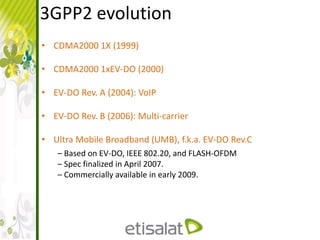
- 5. 3GPP2 evolution • CDMA2000 1X (1999) • CDMA2000 1xEV-DO (2000) • EV-DO Rev. A (2004): VoIP • EV-DO Rev. B (2006): Multi-carrier • Ultra Mobile Broadband (UMB), f.k.a. EV-DO Rev.C – Based on EV-DO, IEEE 802.20, and FLASH-OFDM – Spec finalized in April 2007. – Commercially available in early 2009.
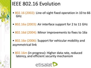
- 6. IEEE 802.16 Evolution • 802.16 (2002): Line-of-sight fixed operation in 10 to 66 GHz • 802.16a (2003): Air interface support for 2 to 11 GHz • 802.16d (2004): Minor improvements to fixes to 16a • 802.16e (2006): Support for vehicular mobility and asymmetrical link • 802.16m (in progress): Higher data rate, reduced latency, and efficient security mechanism
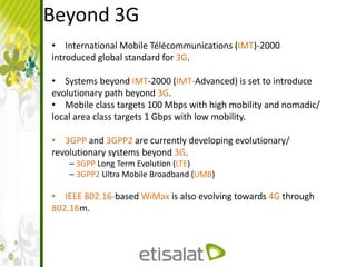
- 7. Beyond 3G • International Mobile Télécommunications (IMT)-2000 introduced global standard for 3G. • Systems beyond IMT-2000 (IMT-Advanced) is set to introduce evolutionary path beyond 3G. • Mobile class targets 100 Mbps with high mobility and nomadic/ local area class targets 1 Gbps with low mobility. • 3GPP and 3GPP2 are currently developing evolutionary/ revolutionary systems beyond 3G. – 3GPP Long Term Evolution (LTE) – 3GPP2 Ultra Mobile Broadband (UMB) • IEEE 802.16-based WiMax is also evolving towards 4G through 802.16m.
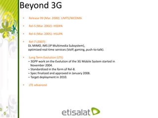
- 8. Beyond 3G • Release 99 (Mar. 2000): UMTS/WCDMA • Rel-5 (Mar. 2002): HSDPA • Rel-6 (Mar. 2005): HSUPA • Rel-7 (2007): DL MIMO, IMS (IP Multimedia Subsystem), optimized real-time services (VoIP, gaming, push-to-talk). • Long Term Evolution (LTE) – 3GPP work on the Evolution of the 3G Mobile System started in November 2004. – Standardized in the form of Rel-8. – Spec finalized and approved in January 2008. – Target deployment in 2010. • LTE advanced
- 9. Course Contents • Historical Vision • LTE Capabilities • System architecture
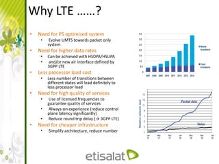
- 11. Why LTE ……? • Need for PS optimized system • Evolve UMTS towards packet only system • Need for higher data rates • Can be achieved with HSDPA/HSUPA • and/or new air interface defined by 3GPP LTE • Less processor load cost • Less number of transitions between different states will lead definitely to less processor load • Need for high quality of services • Use of licensed frequencies to guarantee quality of services • Always-on experience (reduce control plane latency significantly) • Reduce round trip delay (→ 3GPP LTE) • Need for cheaper infrastructure • Simplify architecture, reduce number
- 12. LTE Defined Data Rates • Downlink – 100Mbps theoretical • Uplink – 50Mbps theoretical • Generally we can say the downlink rate relative to HZ 5 bits/s/HZ and for Uplink 2.5bits/s/HZ
- 13. LTE duplexing and accessing • Duplexing Methods – FDD • UL and DL can reach the peak traffic simultaneously – TDD • UL and DL can not reach the peak traffic simultaneously • Accessing techniques – OFDMA for the DL – SC-FDMA for the UL
- 14. Modulation and coding • Adaptive Modulation and Coding – DL Modulations: QPSK, 16-QAM and 64-QAM modulation – UL Modulations: QPSK and 16-QAM – Turbo code
- 15. LTE Maximum Latency (1-2) • For control Plane – The delay of changing the mobile mode from the active to non active and vice versa • If the terminal was in the idle mode it needs 100msec • If the terminal was in the dormant it needs 50msec • For User Plane – Time the terminal takes to transmit small packets to the RAN and Vice versa is 5 msec
- 16. LTE Maximum Latency (2-2) • What is the idle mode – Terminal unknown for the RAN – No Radio resources assigned • What is the dormant mode – Terminal is known for the RAN – No Radio resources assigned
- 17. LTE theoretical Capacity • Active Mode – At 5MHZ BW the Cell can support 200 users simultaneously. – At BW more than 5 MHZ the Cell can support up to 400 Simultaneously terminal. • IDLE Mode – Can support more than 400 Users at the same time
- 18. LTE System Performance targets(1-2) • User throughput – 95% from the users will take average throughput – 5% will be little bit smaller than the average • Spectrum efficiency – It define high spectrum efficiency Bits/MHZ/Cell • Coverage – 5 Km with high throughput – 30 Km with low throughput – 100Km with very low throughput
- 19. LTE System Performance targets(2-2) • Mobility – 0-15km/ hour the more better subscriber behavior. – 120 km/ hour the accepted behavior. – 350 km/ hour very low data rate and data throughput. • Enhanced MBMS – Up to 16 multimedia channels per just one carrier
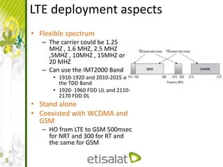
- 20. LTE deployment aspects • Flexible spectrum – The carrier could be 1.25 MHZ , 1.6 MHZ, 2.5 MHZ ,5MHZ , 10MHZ , 15MHZ or 20 MHZ – Can use the IMT2000 Band • 1910-1920 and 2010-2025 are the TDD Band • 1920- 1960 FDD UL and 2110- 2170 FDD DL • Stand alone • Coexisted with WCDMA and GSM – HO from LTE to GSM 500msec for NRT and 300 for RT and the same for GSM
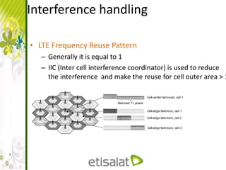
- 21. • LTE Frequency Reuse Pattern – Generally it is equal to 1 – IIC (Inter cell interference coordinator) is used to reduce the interference and make the reuse for cell outer area > 1 Interference handling
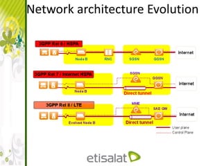
- 22. Architecture and Migration • LTE RAN agreed on the following – Packet bearer support • Real Time • Conversational – Reduce the number of the new interfaces – NO RNC – NO CS-CN – Reduce the single point of failure – NO RNC – Separate the treatment of different types of traffic (O&M, Control and Data) to utilize the BW – Reduce the variable delay and Jitter (TCP/IP) – Agreed QOS between Transmitting end and receiving end – No SHO or Macro diversity – MIMO and Tx diversity techniques used
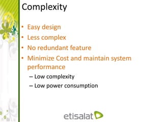
- 23. Complexity • Easy design • Less complex • No redundant feature • Minimize Cost and maintain system performance – Low complexity – Low power consumption
- 26. Course Contents • Historical Vision • LTE Capabilities • System architecture
- 28. 3GPP-LTE Architecture High level (1-2)
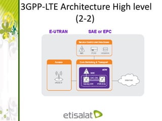
- 29. 3GPP-LTE Architecture High level (2-2)
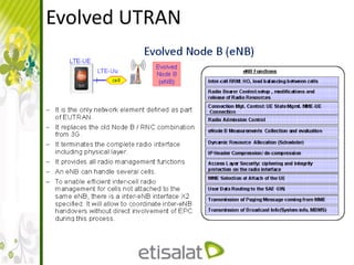
- 31. Evolved UTRAN
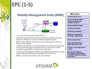
- 32. EPC (1-5)
- 33. EPC (2-5)
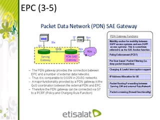
- 34. EPC (3-5)
- 35. EPC (4-5)
- 36. EPC (5-5)
- 37. Interfaces
- 38. UTRAN interfaces
- 39. EPC Interfaces ( 1 – 5 )
- 40. EPC Interfaces ( 1 – 5 )
- 41. EPC Interfaces ( 2 – 5 )
- 42. EPC Interfaces ( 3 – 5 )
- 43. EPC Interfaces ( 4 – 5 )
- 44. EPC Interfaces ( 5 – 5 )
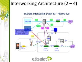
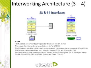
- 45. Interworking Architecture (1 – 4)
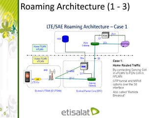
- 49. Roaming Architecture (1 - 3)
- 50. Roaming Architecture (2 - 3)
- 51. Roaming Architecture (3 - 3)
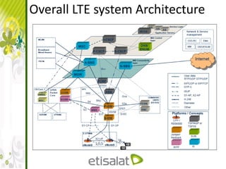
- 52. Overall LTE system Architecture
- 53. Thank You
