SlideShare a Scribd company logo
BRUSH CROWER TYPE(WATER INJECTION)
Prateek Kumar Das
Trident Academy of Technology, Bhubaneswar
CONTENTS
 INTRODUCTION
 WORKING PRINCIPLE
 THERMODYNAMIC ANALYSIS
AND COMPARISION WITH 4-STROKE
 MODIFICATION REQUIRED
 ADVANTAGES
 DRAWBACKS
 CONCLUSION
INTRODUCTION
The concept of six stroke engine was developed in mid 20th
century when pollution due to the conventional IC engine
increased.
The six stroke engine “Using water” was developed
By Brush Crower in 2006 and he patented his product at the end of
2007.
Six stroke engine is a type of internal combustion engine
based on conventional four stroke engine, but it`s additional two
strokes make it more efficient and reduce the emission. The engine
captures heat, which is lost from conventional four stroke cycle and
additional strokes use it to produce power by introducing water
inside the super heated cylinder.
WORKING PRINCIPLES
The working principles of six stroke engine is based on the concept of
four stroke engine but with some modification, another two strokes are added.
SUCTION STROKE
The piston moves from top dead center to the
Bottom dead center and creates vacuum pressure .
So the Air and fuel mixture is sucked in to the
Cylinder.
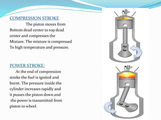
COMPRESSION STROKE
The piston moves from
Bottom dead center to top dead
center and compresses the
Mixture. The mixture is compressed
To high temperature and pressure.
POWER STROKE:
At the end of compression
stroke the fuel is ignited and
burnt. The pressure inside the
cylinder increases rapidly and
it pusses the piston down and
the power is transmitted from
piston to wheel.
EXHAUST STROKE:
The Burnt product is
pushed through the exhaust
valve by the upward movement
of the piston.
SECONDARY POWER STROKE:
At the end of the exhaust
stroke the cylinder temperature
becomes around 900-10000 C. At
this stage water is injected by an
Injector in the form of fine droplets.
The water turns in to vapour
increasing volume around 1600
times when it comes in contact
with the superheated cylinder.
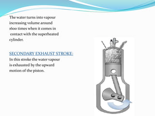
The water turns into vapour
increasing volume around
1600 times when it comes in
contact with the superheated
cylinder.
SECONDARY EXHAUST STROKE:
In this stroke the water vapour
is exhausted by the upward
motion of the piston.
THERMODYNAMIC ANALYSIS
AND
COMPARISION WITH
4-STROKE ENGINE
Work obtained by six stroke is the sum of the both combustion work
and vaporization work. So that the break mean effective pressure will increase.
Pressure and volume diagram
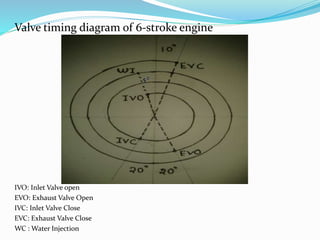
Valve timing diagram of 6-stroke engine
IVO: Inlet Valve open
EVO: Exhaust Valve Open
IVC: Inlet Valve Close
EVC: Exhaust Valve Close
WC : Water Injection
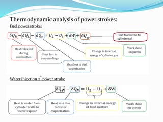
Thermodynamic analysis of power strokes:
Fuel power stroke:
Water injection 2
0
power stroke
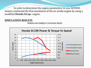
In order to determine the engine parameters, in 2011 HONDA
motors conducted the first simulation of the six stroke engine by using a
modified Honda GC190 engine.
SIMULATION RESULTS
POWER AND TORQUE V/S ENGINE SPEED
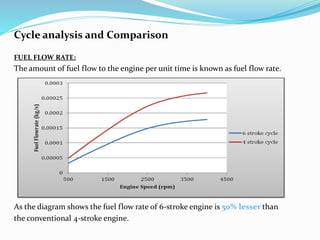
Cycle analysis and Comparison
FUEL FLOW RATE:
The amount of fuel flow to the engine per unit time is known as fuel flow rate.
As the diagram shows the fuel flow rate of 6-stroke engine is 50% lesser than
the conventional 4-stroke engine.
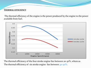
THERMAL EFFICIENCY
The thermal efficiency of the engine is the power produced by the engine to the power
available from fuel.
The thermal efficiency of the four stroke engine lies between 20-30%, where as
The thermal efficiency of six stroke engine lies between 40-50%.
BRAKE SPECIFIC FUEL CONSUMPTION
It is the ratio of fuel consumption per second to the brake power.
As from the diagram the brake specific fuel consumption of 6-stroke
engine is much lower than the conventional six stroke engine.
Factors affecting the engine performance
 Water injecting pump
 Used fuel and lubrication
 Valve timing of the engine
 Temperature of the cylinder wall
MODIFICATIONS REQUIRED
FUELTANK:
 The fuel tank should divided into two parts, as one part will contain fuel and the
other part will contain water.
 The water used should be neutral and distilled.
ENGINE COMPONENTS MATERIAL
The engine components like piston, cylinder , cam, crank, valves etc. are
subjected to severe thermal stress. The thermal stress developed due to the injection
of water into the very hot cylinder. The rapid temperature changes may cause micro
crack and fractures in the engine components as the periodical compression and
expansion takes place.
So the engine components should be designed with high thermal resistive
metal alloys to withstand the stress and prevent failure of engine.
The materials that can be used are…
Silicon Nitride(Si3N4)
Silicon Carbide(SiC)
Zirconia(ZrO2)
Alumina-Tungsten alloy etc.
CAM-SHAFT DESIGN AND VALVE TIMING
The valve control of the 6-stroke engine can be done in two ways.
 by mechanically cam controlled
 by solenoid valve controlled.
The mechanically cam controlled valve is based on the four stroke
design.
In four stroke original angular speed of camshaft is one half of the crankshaft. The
crankshaft rotates once for every two revolution of the crank shaft.
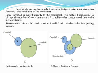
In six stroke engine the camshaft has been designed to turn one revolution
for every three revolution of the crankshaft.
Since camshaft is geared directly to the crankshaft, this makes it impossible to
change the number of teeth on each shaft to achieve the correct speed due to the
size constraint.
To overcome this a third shaft is to be installed with double reduction gearing
system.
(a)Gear reduction in 4-stroke . (b)Gear reduction in 6-stroke.
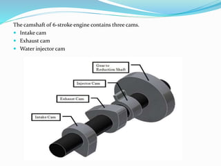
The camshaft of 6-stroke engine contains three cams.
 Intake cam
 Exhaust cam
 Water injector cam
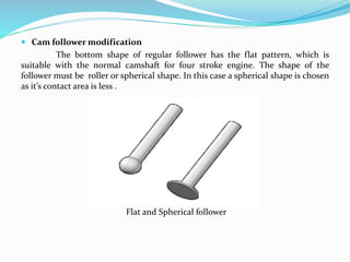
 Cam follower modification
The bottom shape of regular follower has the flat pattern, which is
suitable with the normal camshaft for four stroke engine. The shape of the
follower must be roller or spherical shape. In this case a spherical shape is chosen
as it’s contact area is less .
Flat and Spherical follower
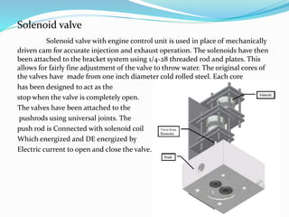
Solenoid valve
Solenoid valve with engine control unit is used in place of mechanically
driven cam for accurate injection and exhaust operation. The solenoids have then
been attached to the bracket system using 1/4-28 threaded rod and plates. This
allows for fairly fine adjustment of the valve to throw water. The original cores of
the valves have made from one inch diameter cold rolled steel. Each core
has been designed to act as the
stop when the valve is completely open.
The valves have been attached to the
pushrods using universal joints. The
push rod is Connected with solenoid coil
Which energized and DE energized by
Electric current to open and close the valve.
Water Injection:
The water injection is done by the help of water injector which is
operated by the cam. This thing can be done more effectively by the use of
Water metering pump or by the progressive cavity pump.
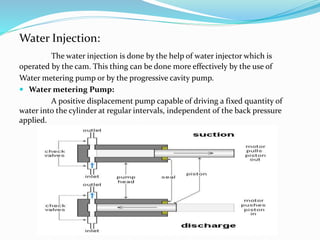
 Water metering Pump:
A positive displacement pump capable of driving a fixed quantity of
water into the cylinder at regular intervals, independent of the back pressure
applied.
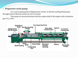
 Progressive cavity pump:
It is a screw pump positive displacement variant. In this the working fluid passes
through series of discrete cavities as rotor is turned.
The pump is to be synchronized with the output shaft of the engine with a reduction
gear of 3:1 ratio.
ADVANTAGES:
 Uses rejected heat from engine
 Fuel economy increases to 60% of conventional engine
 Power output per stroke is more
 Exhaust gas emission is low
 High thermal Efficiency
Drawbacks:
 Early engine starting problem:
As the engine is not sufficiently hot at the starting the water injection stroke
cannot be taken place. So a prime mover is used to run the engine for some
cycle and after heating of the cylinder it is cut out.
 Running problem in cold region:
As the temperature in cold region is low there might be problem in case of
water injection stroke as the cylinder temperature is low.
 Requirement of neutral water:
As the steam is generated in 2
0
power stroke, if the water is not neutralized it
may react with the cylinder wall and with the piston top which results
cavitation and distortion of the metal. It causes the uneven heat transfer
between the water droplets and the cylinder wall which may decrease the
performance of the engine. And it is difficult to carry neutral water all the
times.
CONCLUSION
Six stroke engine has many advantages like high thermal efficiency, low fuel
consumption, high break mean effective pressure, low emission. However drawbacks like
initial starting problem, availability of water are also associated. The starting problem can be
Can be eliminated by using heater or glow plug and coupling a dc motor as prime mover to
the engine. Now a days research and experiments are going on to modify the engine further
and to make it for practical purpose.
REFERENCES :
 15th International Conference on Applied Mechanics and Mechanical Engineering, 29-31
May, 2012,report by M. M. Gasim, L. G. Chui and K. A. Bin Anwar
 Project report on Six stroke engine, Calvin College, ENGR 340
 Thermodynamic analysis testing and validation of six stroke engine Report,
University of Northern Ireland.
 Conklina J. C. and Szybist J. P., "A Highly Efficient Six-Stroke Internal Combustion
Engine Cycle with Water Injection for In-Cylinder Exhaust Heat Recovery", Energy,
Volume 35, Issue 4, pp. 1658-1664 (2010).
 Andrew De Jong, team 6 stroke, https://knightvision.calvin.edu (accessed14/2/2012).
THANK YOU
More Related Content

Six stroke engine(presentation)

  • 1. BRUSH CROWER TYPE(WATER INJECTION) Prateek Kumar Das Trident Academy of Technology, Bhubaneswar
  • 2. CONTENTS  INTRODUCTION  WORKING PRINCIPLE  THERMODYNAMIC ANALYSIS AND COMPARISION WITH 4-STROKE  MODIFICATION REQUIRED  ADVANTAGES  DRAWBACKS  CONCLUSION
  • 4. The concept of six stroke engine was developed in mid 20th century when pollution due to the conventional IC engine increased. The six stroke engine “Using water” was developed By Brush Crower in 2006 and he patented his product at the end of 2007. Six stroke engine is a type of internal combustion engine based on conventional four stroke engine, but it`s additional two strokes make it more efficient and reduce the emission. The engine captures heat, which is lost from conventional four stroke cycle and additional strokes use it to produce power by introducing water inside the super heated cylinder.
  • 6. The working principles of six stroke engine is based on the concept of four stroke engine but with some modification, another two strokes are added. SUCTION STROKE The piston moves from top dead center to the Bottom dead center and creates vacuum pressure . So the Air and fuel mixture is sucked in to the Cylinder.
  • 7. COMPRESSION STROKE The piston moves from Bottom dead center to top dead center and compresses the Mixture. The mixture is compressed To high temperature and pressure. POWER STROKE: At the end of compression stroke the fuel is ignited and burnt. The pressure inside the cylinder increases rapidly and it pusses the piston down and the power is transmitted from piston to wheel.
  • 8. EXHAUST STROKE: The Burnt product is pushed through the exhaust valve by the upward movement of the piston. SECONDARY POWER STROKE: At the end of the exhaust stroke the cylinder temperature becomes around 900-10000 C. At this stage water is injected by an Injector in the form of fine droplets. The water turns in to vapour increasing volume around 1600 times when it comes in contact with the superheated cylinder.
  • 9. The water turns into vapour increasing volume around 1600 times when it comes in contact with the superheated cylinder. SECONDARY EXHAUST STROKE: In this stroke the water vapour is exhausted by the upward motion of the piston.
  • 11. Work obtained by six stroke is the sum of the both combustion work and vaporization work. So that the break mean effective pressure will increase. Pressure and volume diagram
  • 12. Valve timing diagram of 6-stroke engine IVO: Inlet Valve open EVO: Exhaust Valve Open IVC: Inlet Valve Close EVC: Exhaust Valve Close WC : Water Injection
  • 13. Thermodynamic analysis of power strokes: Fuel power stroke: Water injection 2 0 power stroke
  • 14. In order to determine the engine parameters, in 2011 HONDA motors conducted the first simulation of the six stroke engine by using a modified Honda GC190 engine. SIMULATION RESULTS POWER AND TORQUE V/S ENGINE SPEED
  • 15. Cycle analysis and Comparison FUEL FLOW RATE: The amount of fuel flow to the engine per unit time is known as fuel flow rate. As the diagram shows the fuel flow rate of 6-stroke engine is 50% lesser than the conventional 4-stroke engine.
  • 16. THERMAL EFFICIENCY The thermal efficiency of the engine is the power produced by the engine to the power available from fuel. The thermal efficiency of the four stroke engine lies between 20-30%, where as The thermal efficiency of six stroke engine lies between 40-50%.
  • 17. BRAKE SPECIFIC FUEL CONSUMPTION It is the ratio of fuel consumption per second to the brake power. As from the diagram the brake specific fuel consumption of 6-stroke engine is much lower than the conventional six stroke engine.
  • 18. Factors affecting the engine performance  Water injecting pump  Used fuel and lubrication  Valve timing of the engine  Temperature of the cylinder wall
  • 20. FUELTANK:  The fuel tank should divided into two parts, as one part will contain fuel and the other part will contain water.  The water used should be neutral and distilled. ENGINE COMPONENTS MATERIAL The engine components like piston, cylinder , cam, crank, valves etc. are subjected to severe thermal stress. The thermal stress developed due to the injection of water into the very hot cylinder. The rapid temperature changes may cause micro crack and fractures in the engine components as the periodical compression and expansion takes place. So the engine components should be designed with high thermal resistive metal alloys to withstand the stress and prevent failure of engine. The materials that can be used are… Silicon Nitride(Si3N4) Silicon Carbide(SiC) Zirconia(ZrO2) Alumina-Tungsten alloy etc.
  • 21. CAM-SHAFT DESIGN AND VALVE TIMING The valve control of the 6-stroke engine can be done in two ways.  by mechanically cam controlled  by solenoid valve controlled. The mechanically cam controlled valve is based on the four stroke design. In four stroke original angular speed of camshaft is one half of the crankshaft. The crankshaft rotates once for every two revolution of the crank shaft.
  • 22. In six stroke engine the camshaft has been designed to turn one revolution for every three revolution of the crankshaft. Since camshaft is geared directly to the crankshaft, this makes it impossible to change the number of teeth on each shaft to achieve the correct speed due to the size constraint. To overcome this a third shaft is to be installed with double reduction gearing system. (a)Gear reduction in 4-stroke . (b)Gear reduction in 6-stroke.
  • 23. The camshaft of 6-stroke engine contains three cams.  Intake cam  Exhaust cam  Water injector cam
  • 24.  Cam follower modification The bottom shape of regular follower has the flat pattern, which is suitable with the normal camshaft for four stroke engine. The shape of the follower must be roller or spherical shape. In this case a spherical shape is chosen as it’s contact area is less . Flat and Spherical follower
  • 25. Solenoid valve Solenoid valve with engine control unit is used in place of mechanically driven cam for accurate injection and exhaust operation. The solenoids have then been attached to the bracket system using 1/4-28 threaded rod and plates. This allows for fairly fine adjustment of the valve to throw water. The original cores of the valves have made from one inch diameter cold rolled steel. Each core has been designed to act as the stop when the valve is completely open. The valves have been attached to the pushrods using universal joints. The push rod is Connected with solenoid coil Which energized and DE energized by Electric current to open and close the valve.
  • 26. Water Injection: The water injection is done by the help of water injector which is operated by the cam. This thing can be done more effectively by the use of Water metering pump or by the progressive cavity pump.  Water metering Pump: A positive displacement pump capable of driving a fixed quantity of water into the cylinder at regular intervals, independent of the back pressure applied.
  • 27.  Progressive cavity pump: It is a screw pump positive displacement variant. In this the working fluid passes through series of discrete cavities as rotor is turned. The pump is to be synchronized with the output shaft of the engine with a reduction gear of 3:1 ratio.
  • 28. ADVANTAGES:  Uses rejected heat from engine  Fuel economy increases to 60% of conventional engine  Power output per stroke is more  Exhaust gas emission is low  High thermal Efficiency
  • 29. Drawbacks:  Early engine starting problem: As the engine is not sufficiently hot at the starting the water injection stroke cannot be taken place. So a prime mover is used to run the engine for some cycle and after heating of the cylinder it is cut out.  Running problem in cold region: As the temperature in cold region is low there might be problem in case of water injection stroke as the cylinder temperature is low.  Requirement of neutral water: As the steam is generated in 2 0 power stroke, if the water is not neutralized it may react with the cylinder wall and with the piston top which results cavitation and distortion of the metal. It causes the uneven heat transfer between the water droplets and the cylinder wall which may decrease the performance of the engine. And it is difficult to carry neutral water all the times.
  • 30. CONCLUSION Six stroke engine has many advantages like high thermal efficiency, low fuel consumption, high break mean effective pressure, low emission. However drawbacks like initial starting problem, availability of water are also associated. The starting problem can be Can be eliminated by using heater or glow plug and coupling a dc motor as prime mover to the engine. Now a days research and experiments are going on to modify the engine further and to make it for practical purpose.
  • 31. REFERENCES :  15th International Conference on Applied Mechanics and Mechanical Engineering, 29-31 May, 2012,report by M. M. Gasim, L. G. Chui and K. A. Bin Anwar  Project report on Six stroke engine, Calvin College, ENGR 340  Thermodynamic analysis testing and validation of six stroke engine Report, University of Northern Ireland.  Conklina J. C. and Szybist J. P., "A Highly Efficient Six-Stroke Internal Combustion Engine Cycle with Water Injection for In-Cylinder Exhaust Heat Recovery", Energy, Volume 35, Issue 4, pp. 1658-1664 (2010).  Andrew De Jong, team 6 stroke, https://knightvision.calvin.edu (accessed14/2/2012).