SlideShare a Scribd company logo
KERATOMETRY
DR.ANKITA MAHAPATRA
1ST YR PG,OPHTHALMOLOGY
VIMSAR,BURLA
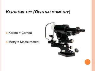
KERATOMETRY (OPHTHALMOMETRY)
 Kerato = Cornea
 Metry = Measurement
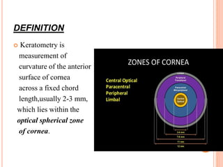
DEFINITION
 Keratometry is
measurement of
curvature of the anterior
surface of cornea
across a fixed chord
length,usually 2-3 mm,
which lies within the
optical spherical zone
of cornea.
PRINCIPLE
 Anterior surface of cornea – CONVEX MIRROR
 From Image Size formed by anterior surface of
cornea (1st Purkinje image) – radius of curvature of
cornea can be calculated
Greater the curvature of cornea, lesser is the image size.
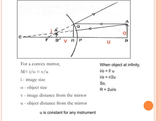
For a convex mirror,
M= i/o = v/u
i - image size
o - object size
v - image distance from the mirror
u - object distance from the mirror
When object at infinity,
i/o = f/ u
i/o = r/2u
So,
R = 2ui/o
i o
v u
u is constant for any instrument
RELATIONSHIP B/W RADIUS OF CURVATURE AND
DIOPTERIC POWER OF CORNEA
D = n-1/r
r=1.3375-1/D mm
D – Dioptric power of cornea
n – Index of refraction of cornea (1.3375)
r – Radius of cornea in metres
DOUBLING PRINCIPLE
Miniature
involuntary eye
movements
during fixation of
eye
Image formed by
anterior surface
of cornea also
moves
(impossible to
measure)
DOUBLING
PRINCIPLE
 Biprisms introduced into the optical system so that 2
images are formed .
 Lower edge of one image coincides with upper edge of
the other.
 If eye moves – both moves
 The prism is moved until the images touch each other.
 Depending on the position of prism – if distance↓,
doubling ↑
Fixed object size
with variable image
size
(Variable doubling)
Fixed image size
with variable object
size
(Fixed doubling)
Eg. Bausch and Lomb
keratometer
Eg. Javal- Schiotz
keratometer
KERATOMETER IS BASED ON 2 CONCEPTS:
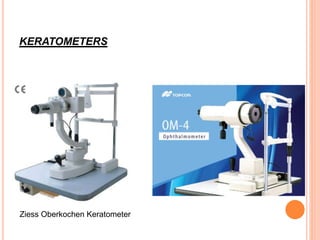
KERATOMETERS
Ziess Oberkochen Keratometer
Humphrey Keratometer Javal Schiotz Keratometer
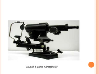
Bausch & Lomb Keratometer
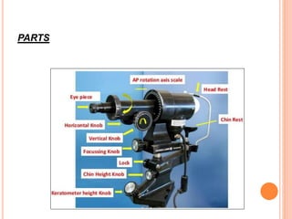
PARTS
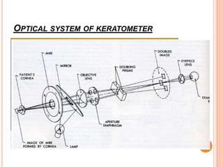
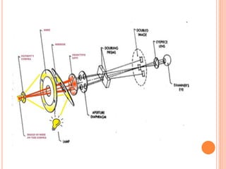
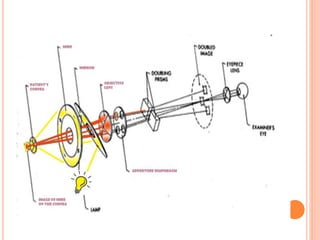
OPTICAL SYSTEM OF KERATOMETER
Keratometry
Keratometry
Keratometry
Keratometry
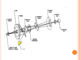
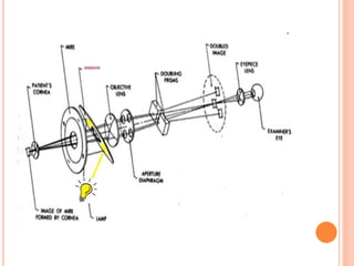
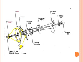
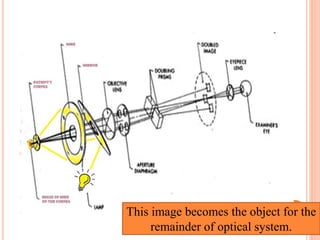
This image becomes the object for the
remainder of optical system.
Keratometry
Keratometry
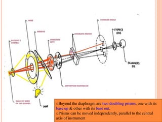
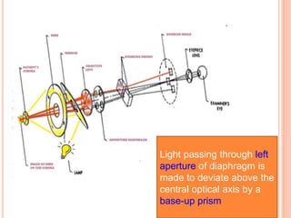
oBeyond the diaphragm are two doubling prisms, one with its
base up & other with its base out.
oPrisms can be moved independently, parallel to the central
axis of instrument
Light passing through left
aperture of diaphragm is
made to deviate above the
central optical axis by a
base-up prism
Light passing through
right aperture is
deviated by base –out
prism, placing the
second image to the
right of the central axis
Light passing through
upper & lower apertures
does not pass through
either prism & an image
is produced on the axis
Keratometry
 Total area of upper & = Area of each of
lower apertures the other two apertures
Therefore, brightness of the images is equal.
 Upper and lower apertures also act as Scheiner’s disc
doubling the central image, whenever the instrument is
not focused precisely on central mire image.
 Thus, image-doubling mechanism is unique in Bausch
and Lomb keratometer, in that double images are
produced side by side as well as at 900 from each other.
 This allows the measurement of the power of
cornea in two meridia, without rotating the
instrument.
Therefore, it is also known as
‘one-position keratometer’
PROCEDURE
1. INSTRUMENT CALIBERATION
Instrument is calibrated before use
White paper held in front of objective lens & a
black line is focused sharply on it
Keratometer is then calibrated with steel balls
Steel ball of known radius of curvature is placed
before keratometer & its value is set on the scale
or dial
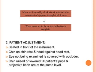
2 .PATIENT ADJUSTMENT:
 Seated in front of the instrument.
 Chin on chin rest & head against head rest.
 Eye not being examined is covered with occluder.
 Chin raised or lowered till patient’s pupil &
projective knob are at the same level.
Mires are focused by clockwise & anticlockwise
movement of eyepiece through trial & error
When mires are in focus, the calibration is
complete.
 Instruct the patient to :
• Keep eyes open wide and blink normally.
• Try not to move the head nor speak.
• Look at the reflection of own eye in the keratometer barrel
3. Focusing of mires :
Mire is focused in the centre of cornea
Patient’s view of mire
The central image is doubled,
indicating that instrument is not
correctly focused on the corneal
image of the mire.
Keratometry
Keratometry
SPHERICAL CORNEA
• No difference in power
b/w 2 principal meridia
• Mires seen as perfect
sphere.
ASTIGMATISM
• Difference in power b/w 2 principal
meridia.
• Horizontally oval mires in WTR
astigmatism.
• Vertically oval mires in ATR
astigmatism.
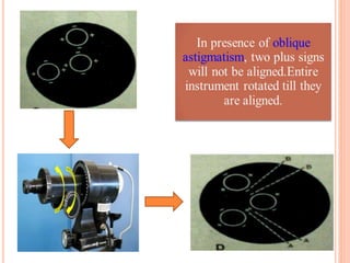
• Oblique astigmatism principal
meridia b/w 300-600 & 120-1500.
IRREGULAR ANTERIOR
CORNEAL SURFACE
• Irregular mires.
• Doubling of mires.
KERATOCONUS
• Pulsating mires(Inclination &
jumping of mires on attempt to adjust
the mires).
• Minification of mires in advanced
cases (K >52 D) due to increased
amount of myopia.
• Oval mires due to large astigmatism.
• Irregular,wavy & distorted mires in
advanced keratoconus.
BAUSCH & LOMB KERATOMETER
 Range – 36.00 to 52.00 D
 Normal values – 44.00 to 45.00 D
 To increase the range – Place +1.25 D lens in front
of aperture to extend range to 61 D
 ADD 9 D
 Place -1.00 D lens in front of aperture to extend
range to 30D
 SUBTRACT 6 D
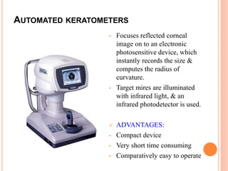
AUTOMATED KERATOMETERS
• Focuses reflected corneal
image on to an electronic
photosensitive device, which
instantly records the size &
computes the radius of
curvature.
• Target mires are illuminated
with infrared light, & an
infrared photodetector is used.
 ADVANTAGES:
• Compact device
• Very short time consuming
• Comparatively easy to operate
 No doubling device is needed.
 Measures angle size in many meridians so it
computes angle as well as power in many
meridians.
 Absence of annoying glare of brightly illuminated
mires.
 Do not calculate clarity of cornea
CLINICAL USES OF KERATOMETERS
1.Helps in measurement of corneal astigmatic error
2.Helps to estimate radius of curvature of the anterior
surface of cornea  Use in contact lens fitting.
3.Monitors shape of the cornea  Keratoconus
Keratoglobus
4.Assess refractive error in cases of hazy media.
5.IOL power calculation.
6.To monitor pre- & post-surgical astigmatism.
7.Used for differential diagnosis of axial versus
curvatural anisometropia.
LIMITATIONS OF KERATOMETRY
 Measurements of keratometer based on false assumption
that cornea is a symmetrical spherical or
spherocylindrical structure,with 2 principal meridia
separated from each other by 900
 Measures refractive status of small central cornea (3-4
mm)
 Loses accuracy when measuring very flat or very steep
cornea
 Small corneal irregularities preclude use of keratometer
due to irregular astigmatism.
 One-position instruments assume regular astigmatism.
 Distance to focal point is approximated by distance to
image.
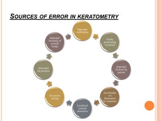
SOURCES OF ERROR IN KERATOMETRY
Improper
calibration
Faulty
positioning
of patient
Improper
fixation by
patient
Accomodat-
ive
fluctuation
by examiner
Localized
corneal
distortion
Excessive
tearing
Abnormal
lid position
Improper
focusing of
corneal
image

More Related Content

Keratometry

  • 1. KERATOMETRY DR.ANKITA MAHAPATRA 1ST YR PG,OPHTHALMOLOGY VIMSAR,BURLA
  • 2. KERATOMETRY (OPHTHALMOMETRY)  Kerato = Cornea  Metry = Measurement
  • 3. DEFINITION  Keratometry is measurement of curvature of the anterior surface of cornea across a fixed chord length,usually 2-3 mm, which lies within the optical spherical zone of cornea.
  • 4. PRINCIPLE  Anterior surface of cornea – CONVEX MIRROR  From Image Size formed by anterior surface of cornea (1st Purkinje image) – radius of curvature of cornea can be calculated Greater the curvature of cornea, lesser is the image size.
  • 5. For a convex mirror, M= i/o = v/u i - image size o - object size v - image distance from the mirror u - object distance from the mirror When object at infinity, i/o = f/ u i/o = r/2u So, R = 2ui/o i o v u u is constant for any instrument
  • 6. RELATIONSHIP B/W RADIUS OF CURVATURE AND DIOPTERIC POWER OF CORNEA D = n-1/r r=1.3375-1/D mm D – Dioptric power of cornea n – Index of refraction of cornea (1.3375) r – Radius of cornea in metres
  • 7. DOUBLING PRINCIPLE Miniature involuntary eye movements during fixation of eye Image formed by anterior surface of cornea also moves (impossible to measure) DOUBLING PRINCIPLE
  • 8.  Biprisms introduced into the optical system so that 2 images are formed .  Lower edge of one image coincides with upper edge of the other.  If eye moves – both moves  The prism is moved until the images touch each other.  Depending on the position of prism – if distance↓, doubling ↑
  • 9. Fixed object size with variable image size (Variable doubling) Fixed image size with variable object size (Fixed doubling) Eg. Bausch and Lomb keratometer Eg. Javal- Schiotz keratometer KERATOMETER IS BASED ON 2 CONCEPTS:
  • 11. Humphrey Keratometer Javal Schiotz Keratometer
  • 12. Bausch & Lomb Keratometer
  • 13. PARTS
  • 14. OPTICAL SYSTEM OF KERATOMETER
  • 19. This image becomes the object for the remainder of optical system.
  • 22. oBeyond the diaphragm are two doubling prisms, one with its base up & other with its base out. oPrisms can be moved independently, parallel to the central axis of instrument
  • 23. Light passing through left aperture of diaphragm is made to deviate above the central optical axis by a base-up prism
  • 24. Light passing through right aperture is deviated by base –out prism, placing the second image to the right of the central axis
  • 25. Light passing through upper & lower apertures does not pass through either prism & an image is produced on the axis
  • 27.  Total area of upper & = Area of each of lower apertures the other two apertures Therefore, brightness of the images is equal.  Upper and lower apertures also act as Scheiner’s disc doubling the central image, whenever the instrument is not focused precisely on central mire image.  Thus, image-doubling mechanism is unique in Bausch and Lomb keratometer, in that double images are produced side by side as well as at 900 from each other.
  • 28.  This allows the measurement of the power of cornea in two meridia, without rotating the instrument. Therefore, it is also known as ‘one-position keratometer’
  • 29. PROCEDURE 1. INSTRUMENT CALIBERATION Instrument is calibrated before use White paper held in front of objective lens & a black line is focused sharply on it Keratometer is then calibrated with steel balls Steel ball of known radius of curvature is placed before keratometer & its value is set on the scale or dial
  • 30. 2 .PATIENT ADJUSTMENT:  Seated in front of the instrument.  Chin on chin rest & head against head rest.  Eye not being examined is covered with occluder.  Chin raised or lowered till patient’s pupil & projective knob are at the same level. Mires are focused by clockwise & anticlockwise movement of eyepiece through trial & error When mires are in focus, the calibration is complete.
  • 31.  Instruct the patient to : • Keep eyes open wide and blink normally. • Try not to move the head nor speak. • Look at the reflection of own eye in the keratometer barrel
  • 32. 3. Focusing of mires : Mire is focused in the centre of cornea Patient’s view of mire The central image is doubled, indicating that instrument is not correctly focused on the corneal image of the mire.
  • 35. SPHERICAL CORNEA • No difference in power b/w 2 principal meridia • Mires seen as perfect sphere. ASTIGMATISM • Difference in power b/w 2 principal meridia. • Horizontally oval mires in WTR astigmatism. • Vertically oval mires in ATR astigmatism. • Oblique astigmatism principal meridia b/w 300-600 & 120-1500. IRREGULAR ANTERIOR CORNEAL SURFACE • Irregular mires. • Doubling of mires. KERATOCONUS • Pulsating mires(Inclination & jumping of mires on attempt to adjust the mires). • Minification of mires in advanced cases (K >52 D) due to increased amount of myopia. • Oval mires due to large astigmatism. • Irregular,wavy & distorted mires in advanced keratoconus.
  • 36. BAUSCH & LOMB KERATOMETER  Range – 36.00 to 52.00 D  Normal values – 44.00 to 45.00 D  To increase the range – Place +1.25 D lens in front of aperture to extend range to 61 D  ADD 9 D  Place -1.00 D lens in front of aperture to extend range to 30D  SUBTRACT 6 D
  • 37. AUTOMATED KERATOMETERS • Focuses reflected corneal image on to an electronic photosensitive device, which instantly records the size & computes the radius of curvature. • Target mires are illuminated with infrared light, & an infrared photodetector is used.  ADVANTAGES: • Compact device • Very short time consuming • Comparatively easy to operate
  • 38.  No doubling device is needed.  Measures angle size in many meridians so it computes angle as well as power in many meridians.  Absence of annoying glare of brightly illuminated mires.  Do not calculate clarity of cornea
  • 39. CLINICAL USES OF KERATOMETERS 1.Helps in measurement of corneal astigmatic error 2.Helps to estimate radius of curvature of the anterior surface of cornea  Use in contact lens fitting. 3.Monitors shape of the cornea  Keratoconus Keratoglobus 4.Assess refractive error in cases of hazy media. 5.IOL power calculation. 6.To monitor pre- & post-surgical astigmatism. 7.Used for differential diagnosis of axial versus curvatural anisometropia.
  • 40. LIMITATIONS OF KERATOMETRY  Measurements of keratometer based on false assumption that cornea is a symmetrical spherical or spherocylindrical structure,with 2 principal meridia separated from each other by 900  Measures refractive status of small central cornea (3-4 mm)  Loses accuracy when measuring very flat or very steep cornea  Small corneal irregularities preclude use of keratometer due to irregular astigmatism.  One-position instruments assume regular astigmatism.  Distance to focal point is approximated by distance to image.
  • 41. SOURCES OF ERROR IN KERATOMETRY Improper calibration Faulty positioning of patient Improper fixation by patient Accomodat- ive fluctuation by examiner Localized corneal distortion Excessive tearing Abnormal lid position Improper focusing of corneal image