X ray tube and production of xrays
•Download as PPTX, PDF•
39 likes•4,097 views

X-rays were discovered accidentally in 1895 by Wilhelm Roentgen. They are produced when a stream of electrons is decelerated upon impact with a metal target in an X-ray tube. The tube contains a cathode that emits electrons via thermionic emission when heated, and an anode that decelerates the electrons. Rotating the anode spreads heat over a larger surface area, allowing higher power outputs. Stationary and rotating anode designs, the line focus principle, and grid control are used to optimize X-ray production and control the electron beam.

X ray tube and production of xrays
- 1. X RAY TUBE and PRODUCTION OF X RAYS . DR INDERMEET MANGAT
- 2. • X-rays were discovered by accident by Wilhelm Conrad Roentgen (1895) while he was experimenting with the passage of electricity through a gas at a very low pressure. • He named those rays as x rays --x as a symbol of the unknown quantity • X rays are produced by energy conversion when a fast moving stream of electrons is suddenly decelerated in the target anode of an x ray tube.
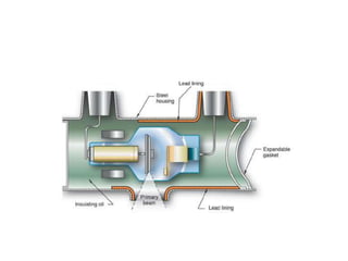
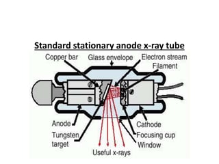
- 3. STRUCTURE OF X – RAY TUBE 1. Pyrex glass 2. Vacuum inside 3. Tube housing - lined by lead - filled with oil 4. Metal bellows within the tube shield 5. Filters 6. Collimators 7. Electrodes- cathode and anode
- 5. Glass enclosure • Made of pyrex glass. • It is necessary to seal the two electrodes of the x ray tube in vacuum because if gas were present inside the tube the electrons that were being accelerated toward the anode target would collide with the gas molecules, lose energy and cause secondary electrons to be ejected from the gas molecules. • So the presence of secondary electrons would result in variation in the number and in the reduced speed of electrons impinging on the target.
- 6. • So the purpose of vacuum in the modern x ray tube is to allow the number and speed of accelerated electrons to be controlled independently.
- 7. CATHODE: • negative electrode • 3 parts- 1. Filament- tungsten wire, source of e- when heated to a temp of atleast 2200 C 2. Connecting wire- supplies voltage (~10 V) & amperage (~3-5 A) 3. Metallic focussing cup- made of Nickel, surrounds the filament, converges e- stream.
- 8. • When a metal is heated its atoms absorb thermal energy and some of the electrons in the metal acquire enough energy to allow them to escape from the surface of the metal by a process of THERMIONIC EMISSION. • So it is defined as the emission of electrons resulting from the absorbtion of thermal energy.
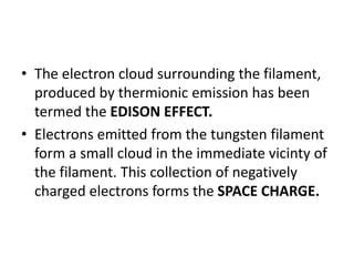
- 9. • The electron cloud surrounding the filament, produced by thermionic emission has been termed the EDISON EFFECT. • Electrons emitted from the tungsten filament form a small cloud in the immediate vicinty of the filament. This collection of negatively charged electrons forms the SPACE CHARGE.
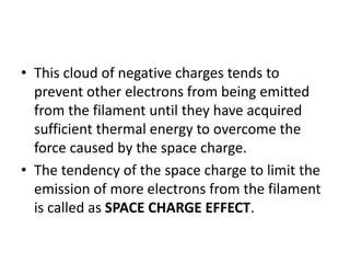
- 10. • This cloud of negative charges tends to prevent other electrons from being emitted from the filament until they have acquired sufficient thermal energy to overcome the force caused by the space charge. • The tendency of the space charge to limit the emission of more electrons from the filament is called as SPACE CHARGE EFFECT.
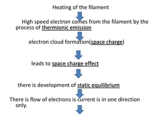
- 11. Heating of the filament High speed electron comes from the filament by the process of thermionic emission electron cloud formation(space charge) leads to space charge effect there is development of static equilibrium There is flow of electrons is current is in one direction only.
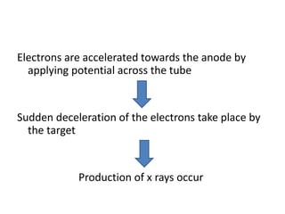
- 12. Electrons are accelerated towards the anode by applying potential across the tube Sudden deceleration of the electrons take place by the target Production of x rays occur
- 13. FOCUSSING CUP • The forces of mutual repulsion and the large number of electrons results in bombardment of large area on anode of the x ray tube. • This is prevented by a structure called focussing cup. It is made of nickel. • Electrical forces of focussing cup cause the electron beam to converge on to target anode in required size and shape.
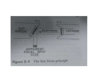
- 14. LINE FOCUS PRINCIPLE • It is the principle which is used to decrease the effective area of focal spot. • The focal spot is the area of the tungsten target (anode) that is bombarded by electrons from the cathode. • Most of the energy of the electrons is converted into heat, with less than 1 % being converted into X rays.
- 15. • Because the heat is uniformly distributed over the focal spot, a large focal spot allows the accumulation of larger amounts of heat before damage to tungsten target occurs. • The problems posed by the need for a large focal spot to allow greater heat loading and the conflicting need for a small focal area to produce good radiographic detail is resolved by the LINE FOCUS PRINCIPLE.
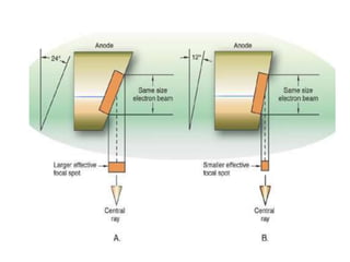
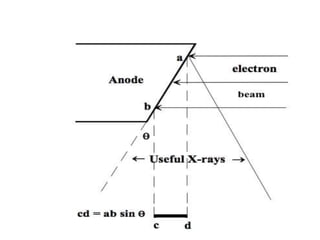
- 16. • THE ELECTRON beam bombards the target, the surface of which is inclined so that it forms an angle with the plane perpendicular to the incident beam. This angle is the anode angle.
- 19. • The anode angle differs according to the individual tube design and may vary from 6 to 20 degree. • Because of this angulation when the slanted surface of the focal spot is viewed from the direction in which x rays emerge from the x ray tube , the surface is foreshortened and appears small.
- 20. • It is evident therefore that the side of the effective or apparent focal spot is considerably smaller than that of actual focal spot. • f= F sin θ • where f is apparent focal spot • F is actual focal spot • Θ is the anode angle. • Thus as the angle of the anode is made smaller the apparent focal spot also becomes smaller.
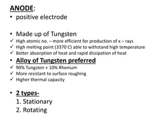
- 22. ANODE: • positive electrode • Made up of Tungsten High atomic no. – more efficient for production of x – rays High melting point (3370 C) able to withstand high temperature Better absorption of heat and rapid dissipation of heat • Alloy of Tungsten preferred 90% Tungsten + 10% Rhenium More resistant to surface roughing Higher thermal capacity • 2 types- 1. Stationary 2. Rotating
- 23. Standard stationary anode x-ray tube
- 24. STATIONARY ANODE • It consists of a small plate of tungsten, 2-3 mm thick that is embedded in a large mass of copper. • The anode angle is usually 15 – 20 degrees. • The small tungsten is embedded /bonded to the much larger copper portion of the anode to facilitate heat dissipation. • Copper is a better conductor of heat than tungsten, so the massive copper anode acts to increase the total thermal capacity of the anode and so speeds its rate of cooling.
- 25. • The actual size of the tungsten target is considerably larger than that the area bombarded by the electron stream. • This is necessary because of the relatively low melting point of copper (1070 deg c). • A single x ray exposure may raise the temperature of the bombarded area of the tungsten target by 1000 deg c or more. • So if the tungsten target were not sufficiently large to allow for some cooling around the edges of the focal spot , the heat produced would melt the copper in the vicinity of the target.
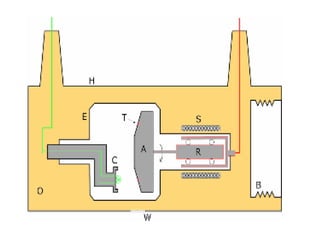
- 26. Rotating anode x- ray tube • Large disc of tungsten/ alloy of tungsten • Beveled edge • Carbon coating • Stem • Rotor • Stator coils • Lubricants
- 28. • The ability of the X ray tube to achieve high X ray output is limited by the heat generated at the anode. • The rotating anode principle is used to produce X ray tubes capable of withstanding the heat generated by large exposures. • The anode of the rotating anode tube consists of a large disc of tungsten which rotates at about 3000 rpms.
- 29. • The tungsten disc has a beveled edge. The angle of the bevel may vary from 6 to 20 degree (same principle as line focus principle).
- 30. • Purpose Of Rotating Anode is to spread the heat produced during an exposure over a large area of anode • If we assume that the filament and focusing cup of the x ray tube produce an electron beam that covers an area of anode 7 mm high and 2 mm wide, the area of the anode bombarded by electrons is represented by a 14 sq mm rectangle.
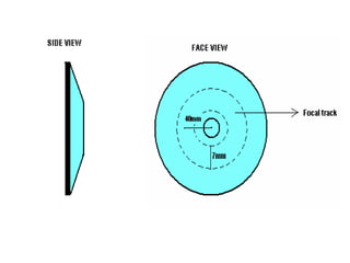
- 31. • If the target is made to rotate at a speed of 3600 rpm, however , the electrons will bombard a constantly changing area of the target. • The total bombarded area of tungsten is represented by a track 7 mm wide that extends around the periphery of the beveled rotating tungsten disc.
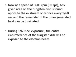
- 33. • Now at a speed of 3600 rpm (60 rps), Any given area on the tungsten disc is found opposite the e- stream only once every 1/60 sec and the remainder of the time- generated heat can be dissipated. • During 1/60 sec exposure , the entire circumference of the tungsten disc will be exposed to the electron beam.
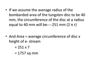
- 34. • If we assume the average radius of the bombarded area of the tungsten disc to be 40 mm, the circumference of the disc at a radius equal to 40 mm will be----251 mm (2 π r) • And Area = average circumference of disc x height of e- stream = 251 x 7 = 1757 sq mm
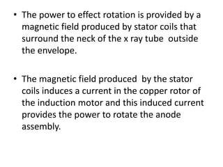
- 35. • The power to effect rotation is provided by a magnetic field produced by stator coils that surround the neck of the x ray tube outside the envelope. • The magnetic field produced by the stator coils induces a current in the copper rotor of the induction motor and this induced current provides the power to rotate the anode assembly.
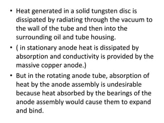
- 36. • Heat generated in a solid tungsten disc is dissipated by radiating through the vacuum to the wall of the tube and then into the surrounding oil and tube housing. • ( in stationary anode heat is dissipated by absorption and conductivity is provided by the massive copper anode.) • But in the rotating anode tube, absorption of heat by the anode assembly is undesirable because heat absorbed by the bearings of the anode assembly would cause them to expand and bind.
- 37. • Because of this problem the stem which connects the tungsten target to the remainder of the anode assembly is made of molybdenum. • Mo has high melting point (2600deg C) and is a poor conductor of heat. • Thus the Mo stem provides a partial heat barrier between the tungsten disc and the bearings of the anode assembly.
- 38. • If the speed of the rotation is increased,the ability of the anode to withstand heat will become greater. • Three modifications to increase velocity: 1. Length of the anode stem to be made short 2. Bearings to be placed as far apart as possible 3. Inertia of the anode is reduced by decreasing the weight of the anode.
- 39. GRID CONTROLLED XRAY TUBES • A grid controlled xray tube contains its own switch,which allows the xray tube to be turned on and off rapidly,as is required with cinefluorography. • A third electrode is used in the grid controlled tube to control the flow of electrons from the filament to the target. This third electrode is the focussing cup that surrounds the filament.
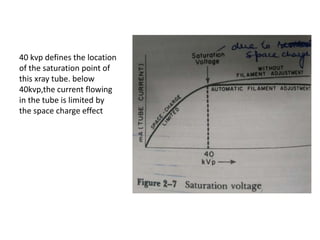
- 40. SATURATION VOLTAGE • If the potential applied across the tube is insufficient to cause almost all electrons to be pulled away from the filament the instant they are emitted,a residual space charge will exist about the filament.
- 41. 40 kvp defines the location of the saturation point of this xray tube. below 40kvp,the current flowing in the tube is limited by the space charge effect
- 42. HEEL EFFECT • The intensity of the X ray beam that leaves the X ray tube is not uniform through out all the portions of the beam. • Rather it depends on the angle at which the X rays are emitted from the focal spot. This variation is termed as HEEL EFFECT. ( variation in the intensity of the X ray beam after it leaves the x ray tube).
- 43. • This is used to advantage when imaging anatomical parts that are unequal in thickness and densities throughout their respective lengths. Eg thoracic vertebrae , humerus, femur, tibia, fibula etc. • The thicker portion of the anatomical part is placed beneath the cathode end of the x ray tube.
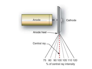
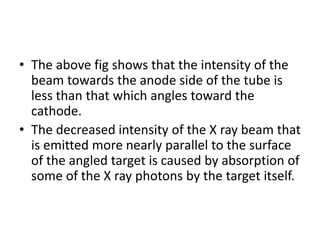
- 45. • The above fig shows that the intensity of the beam towards the anode side of the tube is less than that which angles toward the cathode. • The decreased intensity of the X ray beam that is emitted more nearly parallel to the surface of the angled target is caused by absorption of some of the X ray photons by the target itself.
- 46. • Three clinically important aspects of the heel effect are---- • 1) The intensity of film exposure on the anode side of the X ray tube is significantly less than that on the cathode side of the tube. • 2) the heel effect is less noticeable when larger focus film distances are used. • 3) For equal target film distances , the heel effect will be less for smaller films. • This is because the intensity of X ray beam nearest the central ray is more uniform than that toward the periphery of the beam.
- 47. TUBE HOUSING • X ray tube is always mounted inside a lead lined protective housing that is designed to -Prevent excessive radiation exposure -Prevent electric shock to the patient and operator. • Contains oil in which the tube is bathed.
- 48. PROCESS OF XRAY GENERATION Xrays are generated by two different processes When the high speed electrons lose energy in the target of the xray tube.
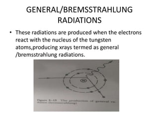
- 49. GENERAL/BREMSSTRAHLUNG RADIATIONS • These radiations are produced when the electrons react with the nucleus of the tungsten atoms,producing xrays termed as general /bremsstrahlung radiations.
- 50. • The electrons when coming towards the anode nucleus are deflected from their path due to positive charge on the nucleus. The electrons may lose energy and be slowed down when their direction changes.The kinetic energy lost by the electron is directly emitted in the form of photon of radiation.
- 51. • The highest energy xray photon leaving the xray tube depends on kvp used. • The lowest energy xray photon leaving the xray tube does not depend on kvp,instead is determined by the filter used. • The wavelength of xrays in the continuous spectrum varies.The variation is produced by the different energies with which the electrons reach the target,and by the fact that most electrons give up their energies in stages.
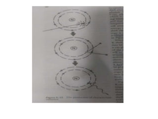
- 52. CHARACTERISTIC RADIATIONS • These radiations result when the electrons bombarding the target eject electrons from the inner orbits of the target atoms. • Xrays produced are called characteristic because these are characteristic of the atom that has been ionised.
- 54. • Characteristic photon energy is equal to the difference between binding energy of the electron shells involved.(Ex. If l shell electron fills k shell vacancy then k-l =characteristic photon energy) • When outer shell electrons fill inner shell vacancies ,a characteristic cascade occurs.This produces several xray photons of different energies.
- 55. • Any outer shell electron can fill an inner shell vacancy,the most likely it is the adjacent shell. • K shell emissions are highest in energy and are the only emissions useful to us. • To get k characteristics we must use at least 70kv(k shell binding energy of tungsten is 69.5kev).
- 56. INTENSITY OF THE XRAY BEAMS • The intensity of the xray beam is defined as the number of photons in the beam multiplied by the energy of each photon. • The higher the atomic number of the target atoms,the greater will be the efficiency of the production of xrays.
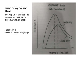
- 57. EFFECT OF kVp ON XRAY BEAM THE kVp DETERMINES THE MAXIMUM ENERGY OF THE XRAYS PRODUCED. INTENSITY IS PROPORTIONAL TO (kVp)2
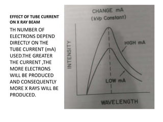
- 58. EFFECT OF TUBE CURRENT ON X RAY BEAM TH NUMBER OF ELECTRONS DEPEND DIRECTLY ON THE TUBE CURRENT (mA) USED.THE GREATER THE CURRENT ,THE MORE ELECTRONS WILL BE PRODUCED AND CONSEQUENTLY MORE X RAYS WILL BE PRODUCED.
- 59. •THANK YOU
Editor's Notes
- #18: Size of projected focal spot is directly related to the sine of the angle of the anode .