Shoulder ultrasound
•Download as PPTX, PDF•
14 likes•2,723 views

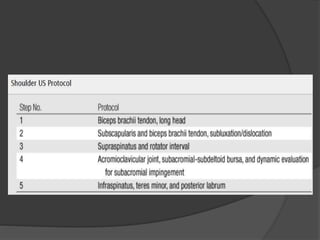
This document provides instructions for performing a shoulder ultrasound examination to evaluate the rotator cuff muscles and tendons. It describes the anatomy of the rotator cuff and positioning for the exam. It then outlines 5 steps to systematically image the biceps tendon, subscapularis, supraspinatus, infraspinatus, teres minor, labrum, and to assess for subacromial impingement. Dynamic maneuvers are used where applicable to evaluate tendon tracking and impingement. Images are included with each step to demonstrate normal ultrasound findings.

Shoulder ultrasound
- 1. Shoulder ultrasound Dr. Mohit Goel JRI, 21 feb, 2013
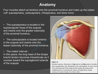
- 3. Anatomy Four muscles attach as tendons onto the proximal humerus and make up the rotator cuff: supraspinatus, subscapularis, infraspinatus, and teres minor. • The supraspinatus is located in the suprascapular fossa of the scapula and inserts onto the greater tuberosity of the proximal humerus. • The subscapularis is located anterior to the scapula and inserts onto the lesser tuberosity of the proximal humerus. • The rotator interval - In this space, the long head of the biceps brachii tendon becomes intraarticular as it courses toward the supraglenoid tubercle of the scapula
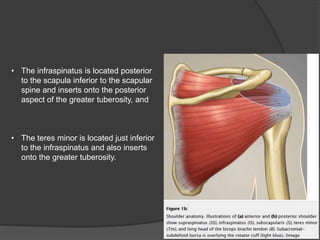
- 4. • The infraspinatus is located posterior to the scapula inferior to the scapular spine and inserts onto the posterior aspect of the greater tuberosity, and • The teres minor is located just inferior to the infraspinatus and also inserts onto the greater tuberosity.
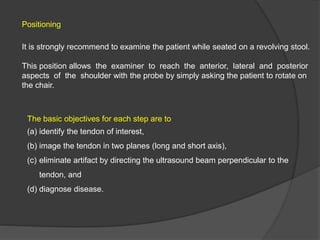
- 5. Positioning It is strongly recommend to examine the patient while seated on a revolving stool. This position allows the examiner to reach the anterior, lateral and posterior aspects of the shoulder with the probe by simply asking the patient to rotate on the chair. The basic objectives for each step are to (a) identify the tendon of interest, (b) image the tendon in two planes (long and short axis), (c) eliminate artifact by directing the ultrasound beam perpendicular to the tendon, and (d) diagnose disease.
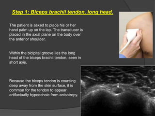
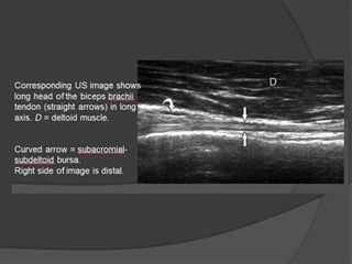
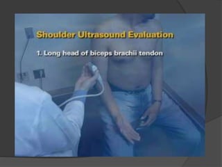
- 6. Step 1: Biceps brachii tendon, long head. The patient is asked to place his or her hand palm up on the lap. The transducer is placed in the axial plane on the body over the anterior shoulder. Within the bicipital groove lies the long head of the biceps brachii tendon, seen in short axis. Because the biceps tendon is coursing deep away from the skin surface, it is common for the tendon to appear artifactually hypoechoic from anisotropy.
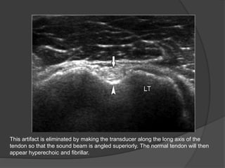
- 7. This artifact is eliminated by making the transducer along the long axis of the tendon so that the sound beam is angled superiorly. The normal tendon will then appear hyperechoic and fibrillar.
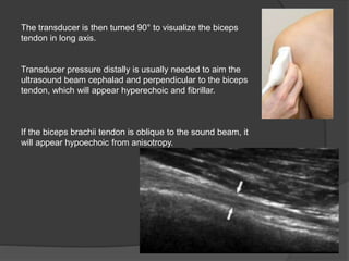
- 8. The transducer is then turned 90° to visualize the biceps tendon in long axis. Transducer pressure distally is usually needed to aim the ultrasound beam cephalad and perpendicular to the biceps tendon, which will appear hyperechoic and fibrillar. If the biceps brachii tendon is oblique to the sound beam, it will appear hypoechoic from anisotropy.
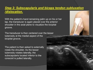
- 11. Step 2: Subscapularis and biceps tendon subluxation /dislocation. With the patient’s hand remaining palm up on his or her lap, the transducer is again placed over the anterior shoulder in the axial plane to visualize the bicipital groove. The transducer is then centered over the lesser tuberosity at the medial aspect of the bicipital groove. The patient is then asked to externally rotate the shoulder. As the lesser tuberosity rotates laterally, the subscapularis located inferior to the coracoid is pulled laterally.
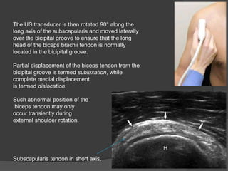
- 12. The US transducer is then rotated 90° along the long axis of the subscapularis and moved laterally over the bicipital groove to ensure that the long head of the biceps brachii tendon is normally located in the bicipital groove. Partial displacement of the biceps tendon from the bicipital groove is termed subluxation, while complete medial displacement is termed dislocation. Such abnormal position of the biceps tendon may only occur transiently during external shoulder rotation. Subscapularis tendon in short axis.
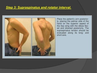
- 14. Step 3: Supraspinatus and rotator interval.
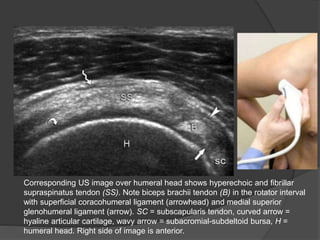
- 15. Corresponding US image over humeral head shows hyperechoic and fibrillar supraspinatus tendon (SS). Note biceps brachii tendon (B) in the rotator interval with superficial coracohumeral ligament (arrowhead) and medial superior glenohumeral ligament (arrow). SC = subscapularis tendon, curved arrow = hyaline articular cartilage, wavy arrow = subacromial-subdeltoid bursa, H = humeral head. Right side of image is anterior.
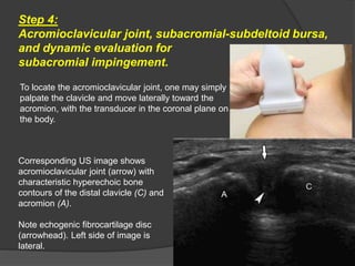
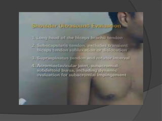
- 17. Step 4: Acromioclavicular joint, subacromial-subdeltoid bursa, and dynamic evaluation for subacromial impingement. To locate the acromioclavicular joint, one may simply palpate the clavicle and move laterally toward the acromion, with the transducer in the coronal plane on the body. Corresponding US image shows acromioclavicular joint (arrow) with characteristic hyperechoic bone contours of the distal clavicle (C) and acromion (A). Note echogenic fibrocartilage disc (arrowhead). Left side of image is lateral.
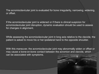
- 18. The acromioclavicular joint is evaluated for bone irregularity, narrowing, widening, or offset. If the acromioclavicular joint is widened or if there is clinical suspicion for acromioclavicular joint disruption, dynamic evaluation should be used to assess for changes in alignment. While assessing the acromioclavicular joint in long axis relative to the clavicle, the patient is asked to move his or her ipsilateral hand to the opposite shoulder. With this maneuver, the acromioclavicular joint may abnormally widen or offset or may cause a bone-on-bone contact between the acromion and clavicle, which can be associated with symptoms.
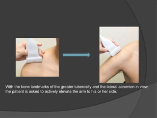
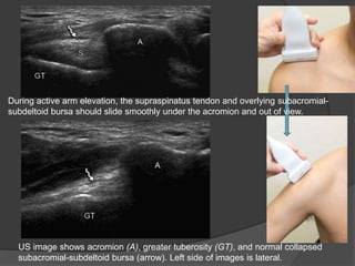
- 19. With the bone landmarks of the greater tuberosity and the lateral acromion in view, the patient is asked to actively elevate the arm to his or her side.
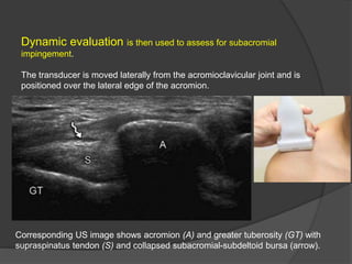
- 20. Dynamic evaluation is then used to assess for subacromial impingement. The transducer is moved laterally from the acromioclavicular joint and is positioned over the lateral edge of the acromion. Corresponding US image shows acromion (A) and greater tuberosity (GT) with supraspinatus tendon (S) and collapsed subacromial-subdeltoid bursa (arrow).
- 21. US image shows acromion (A), greater tuberosity (GT), and normal collapsed subacromial-subdeltoid bursa (arrow). Left side of images is lateral. During active arm elevation, the supraspinatus tendon and overlying subacromial- subdeltoid bursa should slide smoothly under the acromion and out of view.
- 22. Pooling of bursal fluid at the lateral acromion edge or snapping of bursal tissue indicates subacromial impingement. Other findings of impingement include interposition of the supraspinatus tendon between the greater tuberosity and the acromion, as well as direct contact between the greater tuberosity and the acromion. Dynamic evaluation for subacromial impingement can also be completed with the patients raising their arm anterolateral in front of their body, with their hand in pronation.
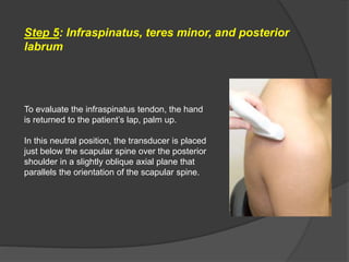
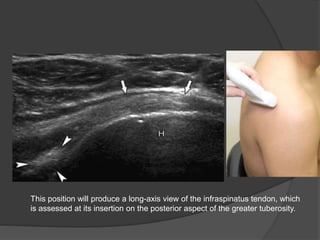
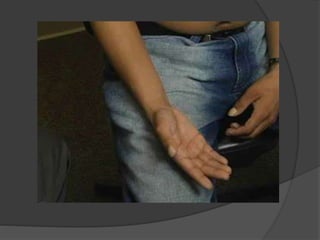
- 24. Step 5: Infraspinatus, teres minor, and posterior labrum To evaluate the infraspinatus tendon, the hand is returned to the patient’s lap, palm up. In this neutral position, the transducer is placed just below the scapular spine over the posterior shoulder in a slightly oblique axial plane that parallels the orientation of the scapular spine.
- 25. This position will produce a long-axis view of the infraspinatus tendon, which is assessed at its insertion on the posterior aspect of the greater tuberosity.
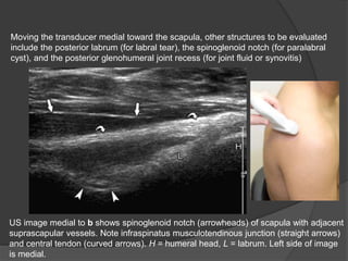
- 26. Moving the transducer medial toward the scapula, other structures to be evaluated include the posterior labrum (for labral tear), the spinoglenoid notch (for paralabral cyst), and the posterior glenohumeral joint recess (for joint fluid or synovitis) US image medial to b shows spinoglenoid notch (arrowheads) of scapula with adjacent suprascapular vessels. Note infraspinatus musculotendinous junction (straight arrows) and central tendon (curved arrows). H = humeral head, L = labrum. Left side of image is medial.
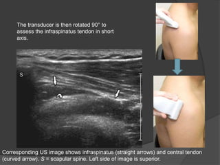
- 27. The transducer is then rotated 90° to assess the infraspinatus tendon in short axis. Corresponding US image shows infraspinatus (straight arrows) and central tendon (curved arrow). S = scapular spine. Left side of image is superior.
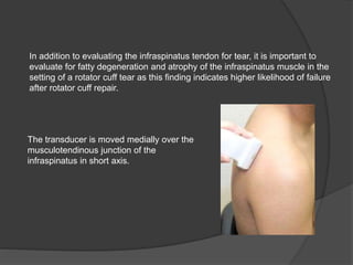
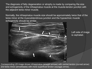
- 28. In addition to evaluating the infraspinatus tendon for tear, it is important to evaluate for fatty degeneration and atrophy of the infraspinatus muscle in the setting of a rotator cuff tear as this finding indicates higher likelihood of failure after rotator cuff repair. The transducer is moved medially over the musculotendinous junction of the infraspinatus in short axis.
- 29. The diagnosis of fatty degeneration or atrophy is made by comparing the size and echogenicity of the infraspinatus muscle at the muscle-tendon junction with the adjacent teres minor muscle. Normally, the infraspinatus muscle size should be approximately twice that of the teres minor at the musculotendinous junction and the hypoechoic muscle echogenicity should be similar. Corresponding US image shows infraspinatus (straight arrows) with central tendon (curved arrow) and teres minor (arrowheads) with more superficial tendon (squiggly arrow). Left side of image is cephalad.
- 31. THANK YOU