I2C, SPI, and UART are commonly used as means for communication between devices within an embedded system due to their simplicity and ease of operation. While they all accomplish a similar goal of sending data, they each have many differences as well as advantages and disadvantages to consider when choosing which to use.
First, we will provide a high-level overview of each of the I2C, SPI, and UART protocols and then provide a comparison between them.
Understanding I2C and SPI Communication Protocols
I2C Protocol
I2C, or Inter-Integrated Circuit, is a simple communication protocol often used in embedded systems as a way to transfer data between a master (or multiple masters) and a single slave (or multiple slaves) device. It is a bidirectional two-wire serial bus that uses serial clock (SCL) and serial data (SDA) wires to send and manage data bit by bit between devices connected to the bus.

In I2C operations, the master controls the exchange of data between the devices. A master device will signal to a slave in order to send data or request a response. To accomplish this, all slave devices must have a unique address that is included in the I2C message.
When sending data over the bus, each I2C message includes an address frame of the slave device and one or more data frames containing the data being transmitted. The message also includes start and stop conditions, read/write bits from either the master or slave, and ACK/NACK bits sent from the receiver for error checking.
I2C is considered to be synchronous, meaning it operates using a serial clock. The clock is driven by the master device which allows the output of bits to be synchronized to the sampling of bits by the clock signal shared between the master and the slave.
The standard data transfer rate of the I2C protocol is 100 kbps, although data speeds of up to 5 Mbps are possible with I2C devices configured in "fast mode" or "ultra-fast mode".
SPI Protocol
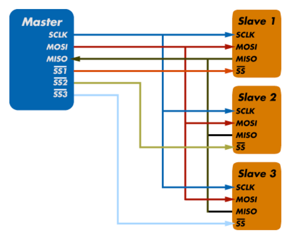
SPI, or Serial Peripheral Interface, is a serial communication protocol often used in embedded systems for high-speed data exchanges between devices on the bus. It operates using a master-slave paradigm that includes at least four signals: a clock (SCLK), a master output/slave input (MOSI), a master input/slave output (MISO), and a slave select (SS) signal. The SCLK, MOSI, and MISO signals are shared by all devices on the bus. The SCLK signal is generated by the master device for synchronization, while the MOSI and MISO lines used for data exchange. Additionally, each slave device added to the bus has its own SS line. The master pulls low on a slave's SS line to select a device for communication.

SPI communication supports full-duplex communication, meaning that both the master and slave can transmit data simultaneously.
The exchange itself has no pre-defined protocol which makes SPI ideal for data-streaming applications. It also has no maximum speed; data speeds in excess of 100 MHz have been achieved.
Understanding UART
UART, or Universal Asynchronous Receiver/ Transmitter, is a physical circuit in a microcontroller or single integrated circuit (IC) that is used to implement serial communication between devices in an embedded system. Essentially, a UART’s main purpose is to transmit and receive serial data.
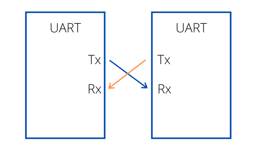
In UART communication, two UARTs communicate directly with each other; the UART on the sender device, or the transmitting UART, receives parallel data from the CPU (microprocessor or microcontroller) and converts it to serial data. This serial data is transmitted to the UART on the receiver device, or the receiving UART. The receiving UART converts the received serial data back to parallel data and sends it to the CPU. In order for UART to convert serial-to-parallel and parallel-to-serial data, shift registers on the transmitting and receiving UART are used.
In UART communication, only two wires are required for communication: data flows from the Tx pin of the transmitting UART (Transmitter Tx) to the Rx pin of the receiving UART (Receiver Rx).

UART data is sent over the bus in the form of a packet. A packet consists of a start bit, data frame, a parity bit, and stop bits. The parity bit is used as an error check mechanism to help ensure data integrity.
UART is considered to be “universal” because the parameters including transfer speed and data speed are configurable by the developer. UART supports bidirectional data transmission, including half-duplex and full-duplex operations. It is also asynchronous, meaning it doesn’t use a clock signal to synchronize the output bits from the transmitting UART to the sampling bits on the receiving UART. Without a clock, the receiving and transmitting UART need to be on the same baud rate, or bit rate. This allows the system to know where and when the bits have been clocked.
Comparing I2C, SPI, and UART Communication
SPI vs I2C
I2C and SPI protocols specifically are often compared as serial communication protocols because they are simple, low-cost, and are both implemented using master/slave architecture including a clock driven by the master for synchronization. While similar in these regards, they also have many differences, and one is often better suited in certain embedded applications.
I2C uses a two-wire interface where slave devices share the data and clock lines. Because of this, adding multiple devices to the bus is simple and reduces complexity of the circuit. I2C also includes flow control and error handling, making it a more reliable protocol. I2C can support multi-masters in a configuration, while SPI can only support one master.
I2C is often a good choice for connecting short-distanced, low-speed devices like microcontrollers, EEPROMs, I/O interface, and other peripheral devices like sensors in an embedded system.
SPI is superior in speed compared to I2C. Its push-pull drivers offer enhanced speed and signal integrity and its full-duplex support means master and slave devices can send data at the same time, allowing for even quicker data exchanges. While SPI has a speed advantage, it is more difficult and costlier to add multiple slave devices to the bus. This is because each slave needs its own slave select line, so the number of wires needed to communicate increases with each device.
SPI is also often used for connecting short-distanced devices within an embedded system, but it is also ideal for memory applications. For instance, many memory devices like SD cards, multi-media cards, EEPROMs, and Flash memory use SPI to store data that can easily be erased/rewritten as needed.
UART vs I2C vs SPI
Unlike communication protocols like I2C and SPI, UART is a physical circuit. While SPI and I2C use a master/slave paradigm to control devices and send data, UART communication incorporates two UART devices to send and receive the data. It also doesn’t operate using a clock so it is necessary for the baud rates of each UART to be within 10% of each other to prevent data loss.
While different in these aspects, UART is similar to I2C and SPI certain ways. For instance, both I2C and UART implement a two-wire interface to send and receive data and is often ideal for low-speed data transmission. UART and I2C also both share error checking mechanisms to help ensure data integrity: I2C uses an ACK/NACK bit and UART uses a parity bit to distinguish any changes in data during transmission.
Also, both UART and SPI support full-duplex communication and cannot support a multi-master configuration. However, SPI is much faster in speed compared to UART and I2C.
UART is often used as a form of device-to-device communication in computer and microcontroller applications.
Debugging and Developing I2C and SPI Systems
Communication protocols like I2C and SPI are an essential component to an embedded system’s performance, so it’s important that the bus is operating correctly without errors. Without the right tools, finding bus and data errors can be challenging. That’s why using debugging and development tools are essential for an embedded system engineer’s toolbox.
Total Phase offers numerous tools to develop and debug I2C and SPI systems, including host adapters and protocol analyzers, including the Aardvark I2C/SPI Host Adapter, the Cheetah SPI Host Adapter, the Promira Serial Platform, and the Beagle I2C/SPI Protocol Analyzer.
The Aardvark I2C/SPI Host Adapter is a general-purpose host adapter supporting I2C and SPI protocols and can operate up to 800 kHz as an I2C master and slave. It is often used to test I2C systems by emulating master/slave configurations.
The Cheetah SPI Host Adapter is designed to support high-speed programming applications, allowing users to signal up to 40 MHz as a master SPI device.
The Promira Serial Platform is Total Phase’s most advanced serial device. With its field upgradeable platform, users can configure the device with applications that allow users access to I2C and SPI protocols, various speeds, and other capabilities. Depending on the application and level, this device can support up to 3.4 MHz as an I2C master and slave.
The Beagle I2C/SPI Protocol Analyzer can non-intrusively monitor I2C and SPI traffic in real time. It can monitor I2C up to 4 MHz and offers flexible search and filtering capabilities.
For any further questions on which I2C or SPI development tool is best for your own project requirements, please contact us at [email protected].