Definition: The devices that are designed to provide zero-voltage or zero-current switching are known as Resonant Converters. These converters are basically electric power converters that contain a network of inductors and capacitors that is specifically tuned to resonate at a particular frequency.
In an electric circuit, resonant converters are incorporated to somewhat lessen the chances of switching losses in devices like MOSFET or IGBT. These are regarded as electrical inverters that work on resonant current oscillation.
Introduction
We are already aware of the fact that by the use of switching devices the load current can switch on or switch off the overall load current that is flowing through the circuit at a high value of the rate of change of current with time i.e., di/dt. The devices that are designed to deal with high di/dt also come across high-voltage stresses during the operation. So, this leads to rise the power losses associated with the switching devices.
In case, the size of the components is reduced then this enhances the switching frequency. At relatively high frequency, the losses introduced due to switching as well as the high-voltage stress also exhibit a considerable increase. Not only this but high di/dt and dv/dt which are the result of turning on and off of switching devices may lead to cause electromagnetic interference.
The above-discussed drawbacks can be dealt in a way that the switch in the converter will be turned on and off when the voltage and current across the device will be zero at the time when switching is performed. Thus, it is said that the converters that offer zero-voltage or zero-current switching are regarded as resonant converters. The necessary resonance that these converters require is provided by L and C components present in the circuit.
Resonant Converter Structure
A conventional resonant converter mainly has 3 sections namely, switch network, resonant tank, and rectifier network. The switch network is responsible for producing pulsating voltage and current from the DC voltage or current source. The resultant output of the switch network is further provided to the rectifier network. The pulsating voltage or current that is fed to the rectifier network is responsible for the rectification of the pulsating dc signal into DC voltage or current.
The resonant tank is the combination of inductor and capacitor and performs the action of modulating the gain amplitude of the signal by varying the frequency of the pulsating signal.
Sometimes in order to avoid the saturation of the transformer a DC blocking capacitor (Cb) is used between the switch network and rectifier network.

Let us now proceed to understand the resonant converters that possess zero-current switching (ZCS) and zero-voltage switching (ZVS).
Zero-Current Switching Resonant Converters
The zero-current switching converters are of two types namely L-type and M-type. In both the circuit configurations, L and C are the necessary components that form the series resonant circuit. The presence of the inductor limits the rate of change of switching current in the circuit. Let us now discuss both the circuit configurations individually.
L-type ZCS Resonant Converters
Here the switching device used in the circuit configuration can be GTO, thyristor, BJT, MOSFET, IGBT, etc. The figure below represents the circuit for the L-type ZCS resonant converter:

The selection of switching devices depends on the frequency range of operation. Basically, for the low-frequency range of operation, thyristor, transistor, or IGBT can be used. While in the megahertz range, power MOSFETs are used. The resonant circuit is the one consisting of L and C connected across the dc source Vdc whereas the filter circuit over here is the one consisting of L1 and C1 connected across the load.
Initially, in the steady-state condition constant current I0 flows through the load. Also, switch S in the circuit is open, so the resonant circuit parameters will be iL = 0 across the inductor and vc will be 0 across the capacitor and the load current I0 easily flows through the diode D.
M-type ZCS Resonant Converter
The figure represented below shows the circuit configuration of M-type zero-current switching resonant converter:

Like the previously discussed L-type configuration, here also L and C constitute the resonant circuit while L1 and C1 constitute the filter circuit. Capacitor C is present in parallel orientation across the series combination of switch S and inductor L.
Zero-Voltage-Switching Resonant Converters
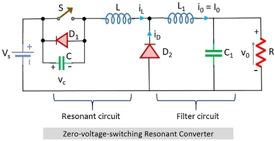
This type of resonant converter is one that consists of a diode and capacitor that form a parallel connection with the switch S. Similar to the previously discussed case of zero-current-switching resonant converter here also the components L and C constitute the resonant circuit while L1 and C1 form the filter circuit. Here the resonant capacitor is incorporated in the circuit so as to have zero voltage across the switch.

In this circuit, the path through which the load current I0 flows is provided by the freewheeling diode. The operation of this circuit is concerned with the fact that the switch will get turned on and off when there will be zero voltage across the switch.
How zero-current-switching is different from zero-voltage-switching Converters?
In the zero-current-switching mode, the switch is made to withstand the current of value I0 + Vs/Z0. For the device to get turned off naturally, the value of Vs/Z0 should be higher than I0. This means that the load current is specified by an upper limit in the case of a zero-current-switching converter.
In the zero-voltage-switching mode, here the switch will be designed to handle peak voltage Vs + I0Z0. This implies that peak switch voltage shows dependency on load current I0. In order to change the load current considerably, there must exist a large voltage across the switch. As here the voltage acts as the dominating factor thus, the zero-voltage-switching converters suit constant load applications.
Hence, generally, zero-voltage-switching is preferred over zero-current-switching frequencies and the reason for the same is the internal capacitances that exist with the switch.
Leave a Reply