Exploring IC 7493: A Deep Dive into 4 Bit Binary Counter Circuit
Update Time: 2023-10-23 14:00:26
Contents
Digital circuitry offers a gateway to a realm of ingenuity and artistic expression. A cornerstone element deeply intertwined with these designs is the IC 7493 4-Bit Binary Counter. Within this article, we embark on a systematic exploration, guiding you through crafting a high-performance circuit utilizing the IC 7493. Whether you're taking your first steps or are already a seasoned fan of electronic systems, this manual empowers you with the insight and aptitude to conceive a potent 4-bit binary counter circuit.
Introduction
Counters occupy a vital position within the domain of digital electronics. They fulfill a foundational role by capturing the occurrences of specific events. Counters serve the purpose of enumeration and extend their utility to frequency measurement and temporal assessment. Furthermore, these versatile tools facilitate mathematical operations, dynamically modifying the numeric value in response to preceding states. The IC 7493 proves its versatility as an integrated circuit, functioning adeptly as a 4-bit binary tally device. Its capacity to enumerate and restore values, synchronized by temporal cues, establishes it as a pivotal element in the composition of digital circuitry.
What is Binary Counter?
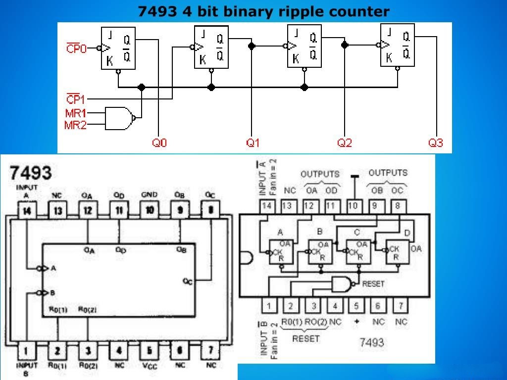
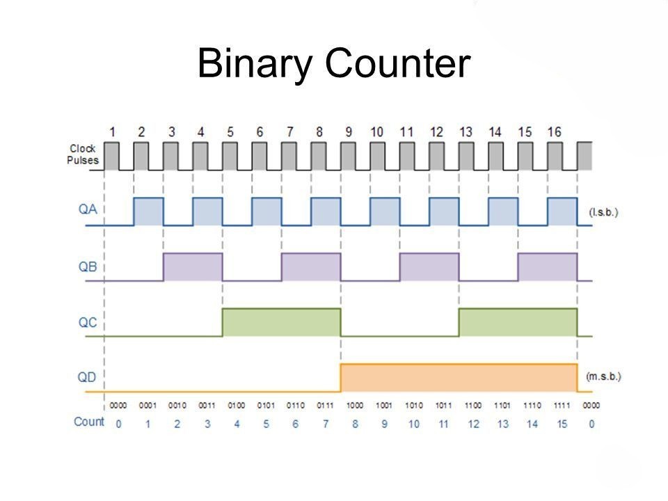
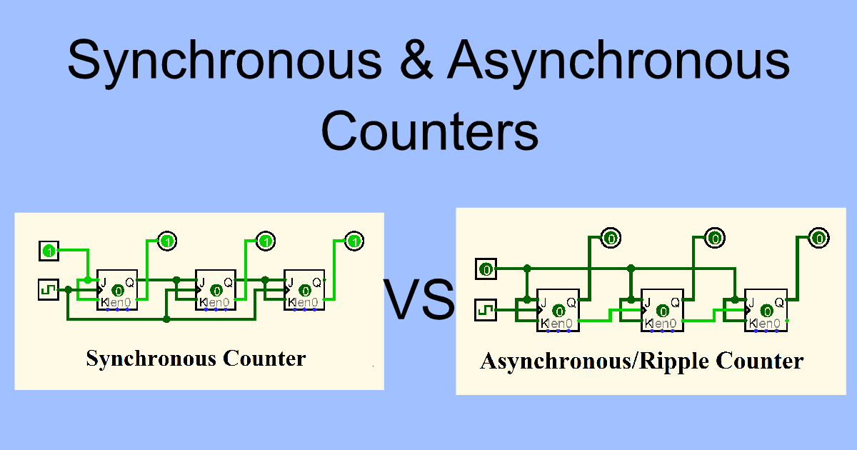
A binary counter functions as a hardware circuit, intricately constructed using an array of flip-flops. Sequentially, the output of each flip-flop channels into the input of the succeeding flip-flop. The terminology of a binary counter as asynchronous or synchronous is contingent upon the interlinking setup of these flip-flops.
Binary Counter Circuit
Specifications of 74LS93 IC
4-bit binary counter
Ripple carry output for cascading multiple counters
Typical Operating Voltage: 5V
The input clock frequencies are 32MHz and 16MHz
Output High Voltage: 3.5V
Output Low Voltage: 0.25V
Output current when high: -0.4mA
Output current when low: 8mA
Contained within a 14-pin DIP (Dual in-line Package), this is the nature of the IC
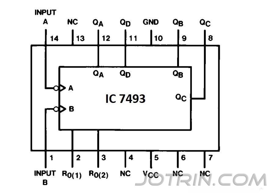
IC 7493 Pin Description:
Pin Number Pin Name Description 4, 6, 7, 13 NC No connection 8, 9, 11, 12 Q0, Q1, Q2, Q3 Output pins 10 Ground Ground of the system 14 CLK A Clock input - divide by 2 1 CLK B Clock input - divide by 8 2,3 R Reset - Clear input 5 Vcc Supply voltage - 4.5V to 5.5V
Hardware Components
These components are essential for making Binary Counter Circuit:
S.no Component Value Qty 1. IC HD74HC4040 1 2. IC NE555 timer 1 3. LEDs - 8 4. Ceramic Capacitor 0.1uF 1 5. Electrolytic Capacitor 10uF 1 6. Resistor 1KΩ, 10KΩ, 220Ω 2, 1, 1 7. Battery 6V 1
7493 IC Pin Diagram
IC 7493 Applications
Frequency division and counting applications
This IC used to create a long time delay
It is used in timing related application
By using this IC, few microcontroller-based applications can be done
Digital clocks and timers
Frequency synthesis
Sequence generation
This IC is commonly used in divide by 2, divide by 8, and divide by 16 applications
Other Counter ICs
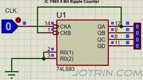
4 Bit Binary counter using IC 7493
The diagram visually depicts a 4-bit sequential tally device implemented using the 7493 integrated circuit. The configuration encompasses dual counters: a modulus-2 counter and a modulus-8 counter. Initial analysis reveals that CLKA corresponds to the clock signal of the first counter, whereas CLKB pertains to the clock input of the second counter. As part of the enabling process, R0(1) and R0(2) interfaces link to the ground, effectively initializing the counter IC. Notably, QA, QB, QC, and QD denote the quadruple outputs generated by this IC. The binary spectrum spanned encompasses the numerical range from 0 to 15, or from 0000 to 1111.
Notably, distinct utility surfaces when deploying the circuit as a Mod-8 counter, a transformation accomplished solely by invoking CLKB. The resulting operation confines the enumeration to 0 to 7, or equivalently, 000 to 111.
Furthermore, a third operational mode assumes the guise of a Mod-2 configuration, a state alteration from 0 to 1. This mode is harnessed to subdivide the input frequency, effectively halving its magnitude.
IC 7493 Datasheet
Check the IC 7393 datasheet (PDF) from TI.
Proteus Simulation
Read More
Previous: CD4017BE CMOS Counter: Circuit, Pinout and Datasheet
Next: Synchronous and Asynchronous Counter: Key Differences Explained
FAQ
- How to make a binary counter?
A binary counter may emerge through the assembly of J-K flip-flops, wherein the product of one cell is conveyed to the clock input of its successive counterpart. To trigger a toggle upon each clock cycle, J and K inputs across all flip-flops assume a value of 1.
- What is the decade counter using IC 7493?
In its configuration, the 7493 operates as a 4-bit binary counter, facilitating counting up to 15. Consequently, a concatenation of M 7493 units yields the ability to count across the range of 0 to 16M-1. In comparison, the 7490 is a decade enumerator or a solitary BCD (binary coded decimal) counter, with a counting capacity spanning 0 to 9. In the case of M cascaded 7490 units, the cumulative range expands to encompass 0 to 10M-1.
- What is IC 74LS93?
The 74LS93 embodies a 4-bit binary counter comprised of a pair of ascending counters. Encased within the IC lies a mode-2 ascending counter and an octupling ascending counter. These elements can coalesce to operate as an octupling counter or, alternatively, facilitate applications involving halving or octupling divisions. This construction employs four JK Flip Flops as its foundation.
- What does IC 7493 consist of?
4 JK Flip Flop.
- What is binary counter in embedded systems?
The Binary Counter is harnessed for crafting ascending, descending, and alternating enumerators, yielding output sequences spanning widths of up to 256 bits. Accommodating a singular threshold signal, users can program its activation upon reaching a specified count.
- How does the binary counter work as a frequency divider?
A binary counter can find application in crafting a frequency dividing mechanism, achieved by directing the output of a given flip-flop to serve as the clock signal for an alternate circuit. Meanwhile, a numerical enumerator, alternatively labeled as a BCD enumerator, engages in decimal enumeration from 0 to 9. This is executed by allocating four bits or flip-flops per individual digit.
Ratings and Reviews
Related Products
-

TJA1040T
NXP/PHILIPS
High speed CAN transceiver > -
TDA8924TH
NXP/PHILIPS
2 × 120 W class-D power amplifier > -

TDA8920BJ
NXP/PHILIPS
2 X 100 W class-D power amplifier > -
TDA7021T
NXP/PHILIPS
FM radio circuit for MTS > -
TDA19997HL/C1
NXP/PHILIPS
Triple input HDMI 1.4a compliant receive > -

TDA1520B
NXP/PHILIPS
20 W HI FI AUDIO POWER AMLIFIER > -
SCC2692AC1N40
NXP/PHILIPS
DUAL UART, FIFO, 115KBAUD 5.5V No. of Ch > -

SC28L92A1B
NXP/PHILIPS
3.3V-5.0V Dual Universal Asynchronous Re > -

SAA7121H
NXP/PHILIPS
Digital video encoder > -

SA612AD
NXP/PHILIPS
RF Mixer LP VHF DBL-BAL W/OSC > -
PCF8576CH
NXP/PHILIPS
Universal LCD driver for low multiplex r > -
PCF8563T
NXP/PHILIPS
Real-time clock/calendar > -
PCF7946AT
NXP/PHILIPS
IC MCU TRANSPONDER 14SOIC > -
P89LPC922FN
NXP/PHILIPS
8-bit Microcontrollers - MCU 8K FL/256B > -
P82B96TD
NXP/PHILIPS
BI-DIRECTIONAL BUFFER, DUAL, No. of Chan >


 ALL CATEGORIES
