Preprint
Article
Large Strain Nonlinear Consolidation of Sand-Drained Foundations Considering Vacuum Preloading and the Variation of Radial Permeability Coefficient
Altmetrics
Downloads
69
Views
32
Comments
0
A peer-reviewed article of this preprint also exists.
This version is not peer-reviewed
Submitted:
22 August 2023
Posted:
23 August 2023
You are already at the latest version
Alerts
Abstract
The vacuum preloading method effectively strengthens the soft soil foundations with vertical drainage, which will produce a smear effect when laying sand drains. Meanwhile, the seepage of pore water and soil deformation during consolidation exhibits nonlinear characteristics. Therefore, based on Gibson's 1D large strain consolidation theory, this paper developed a more generalized large strain radical consolidation model of sand-drained soft foundations under free strain assumption. In this system, the double logarithmic compression permeability relationships for soft soils with large strain properties, the variation of the radical permeability coefficient in the smear zone, and the effect of the non-Darcy flow were all included. Then, the partial differential control equations were numerically solved by the finite difference method and validated with existing radical consolidation test results and derived analytical solutions. Finally, the influences of relevant model parameters on consolidation are discussed. The analysis shows that the greater the maximum dimensionless vacuum negative pressure P0, the faster the consolidation rate of sand-drained foundations. Meanwhile, the decrease in the negative pressure transfer coefficient k1 will result in a decreasing final settlement amount. Moreover, the consolidation rate of sand-drained foundations is slower considering the non-Darcy flow, but the final settlement is unaffected.
Keywords:
Subject: Engineering - Civil Engineering
1. Introduction
The vacuum preloading method is one of the effective methods to treat soft soil ground with the drainage consolidation method. Its principle is to produce negative pressure in the soil as a load through vacuum pumping, and then the water in the soil pores is drained so that the ground soil is consolidated and the strength is improved. Previous studies [1,2,3,4] have shown that the vacuum preloading method will produce large deformations when dealing with soft soils with large void ratios and the permeability coefficient decreases with the decrease of the soil void ratio. Meanwhile, the construction disturbance of the installed sand drain produces a smear effect, so the variation of the radical permeability coefficient within the smear zone should also be considered. Meanwhile, it is also indisputable that water seepage in soft clay deviates from Darcy flow [5,6,7]. Therefore, a more generalized large strain nonlinear consolidation model of soft soil foundations with vertical drains is established in this paper, considering the coupled effect of the nonlinear compression relationship and permeability relationships, variable permeability coefficient in the smear zone, and non-Darcy flow effect. It is expected to simulate the radial drainage consolidation of deep clayey foundations more truly.
For the study of vacuum preloading on sand-drained foundations, relevant scholars have conducted much research and achieved rich results [8,9,10,11,12]. Among them, studies [8,9] developed Terzaghi’s 1D consolidation system incorporating vacuum preloading. Chai et al. [10] established a method for estimating the final vacuum pressure distribution and proposed the corresponding model for the vacuum-drain consolidation-induced settlement curves. Indraratna et al. [11] and Geng et al. [12] respectively deduced the analytical solution of vertical drains consolidation foundations with linear attenuation of vacuum preloading, conventional and point array vacuum preloading. However, these studies have neglected the large-strain consolidation characteristics of soft clayey soils, and research reveals that the small strain theory would not be suitable for highly compressible soil such as soft clayey soils with large-stain properties. [13,14]. In this regard, [15] investigated large-strain nonlinear consolidation of sand-drained foundations in clay by assuming that the void ratio varies exponentially with effective stress. Perera et al. [16] derived the large strain consolidation analytical solution for vacuum preloading incorporating the semi-logarithmic nonlinear compression relationship and soil disturbance. Geng et al. [17] and Nguyen et al. [18] respectively studied the nonlinear large strain consolidation of sand-drained foundation considering self-weight and well resistance decay over time by using a semi-logarithmic relationship (i.e., and ). Walker et al. [19] presented an approximate solution for the consolidation of sand-drained foundations considering smear zone overlap. As research deepens, R. Butterfield [20] proposed to apply double logarithmic compression and permeability relationships (i.e., Eqs. (2) and (3) ) to analyze the consolidation problem and pointed out that this double logarithmic form relationship can be well consistent with the test results for soft clayey soils under large strain scenario. Tavenas et al. [21] also demonstrated that the semi-logarithmic form relationships only satisfy linear relationships in low-strain categories below 20%. Based on double logarithmic compression and permeability relationships, Li et al. [22] initially developed the 1D large strain consolidation for soft ground and derived the corresponding analytical solutions. However, studies above on sand-drained foundations consolidation often assume that pore water seepage in the soil is consistent with Darcy flow.
According to the research results of indoor tests [5,6,7], it was found that the pore water seepage exhibited nonlinear characteristics under low hydraulic gradients. Among them, considering the non-Newtonian fluid characteristics of soil, Swartzendurber [6] summarized different region’s minoring data and proposed a continuous mathematical expression flow rule with only two flow parameters. This flow relationship could fit well with the test data and easily be applied in practical engineering. Based on this, scholars [23,24] have conducted the 1D consolidation considering this flow relationship and obtained a more generalized understanding of 1D consolidation characteristics.
In summary, although the research on sand drain consolidation under vacuum preloading has achieved certain results, the influence of the nonlinearity compression and permeability relationships, radical permeability coefficient variation, and non-Darcy flow still has not be considered simultaneously. Therefore, based on Gibson [13]'s 1D large strain consolidation theory and Barron [25]'s free strain assumption, an improved large strain vacuum preloading consolidation equation of soft ground with sand drain is established and solved by the finite difference method. The double logarithmic compression and permeability relationships for large voids rations soft clays, the three different permeability variation modes in smear zone, and non-Darcy flow with continuous function form were also included in this system. Based on the proposed vertical drains model solutions, relevant parameters affecting the consolidation of soft foundations with sand drain are furtherly analyzed.
2. Large Radical Strain Consolidation Model with Sand Drains
2.1. Problem Description
As shown in Figure 1, assuming the thickness of a homogeneous soft soil foundation is H, a sand drain is installed in the foundation for drainage consolidation. Considering the smear effect caused by construction disturbance, the whole influence area of radial seepage is divided into a smear zone and an undisturbed zone. The radius of the sand drain, smear area, and influence area are rw, rs, and re, respectively. r and z denote the radial and vertical coordinates, respectively, and -pv(z) is the vacuum negative pressure acting on the sand drain zone. The edge of the sand drain is a fully pervious boundary, and the outermost periphery of the weak smear area is an impermeable boundary. q(t) is the overload load on the foundation surface (see Figure 2), where t1 is the completion of the single-loading time, q0 is the initial load value, and qu is the final value.
2.2. Basic Assumptions
To facilitate the solution, the following assumptions are made on the basis of Gibson's 1D large deformation consolidation theory and Barron's free strain consolidation theory:
(1) The soil particles only move vertically and the radical geometric deformation is ignored.
(2) In the process of soft foundations with sand drain consolidation, only radical seepage is considered, and vertical seepage is not considered.
(3) As shown in Figure 3, it is assumed that the seepage of pore water corresponds to the non-Newtonian index flow [6], that is:
where v is the seepage velocity; i is the hydraulic gradient; kr is the radial permeability coefficient; i0 is the non-Newtonian index.
The nonlinear relationship of soft soils can be simulated by the double logarithmic compression and permeability relationship proposed by R. Butterfield (1979), i.e.,
where e0 and e are the initial void ratio and the void ratio at any time, respectively. σ0′ and σ′ is the initial effective stress and the initial effective stress at any time. kr is the radical permeability coefficient at the radius of the undisturbed area at any time, and kr0 is the initial radical permeability coefficient. Ic is the slope of the lg(1+e)-lg σ′ linear relationship, α is the reciprocal of the slope of the linear relationship lg(1+e)-lg kr. For convenience, Ic and α are expressed by compression index and permeability index.
(5) Suppose the vacuum negative pressure at the sand well boundary changes from -p0 to -k1p0 along the depth, i.e., Eq. (4):
where p0 is the vacuum preloading value at the foundation's top surface, k1 is the negative pressure transfer coefficient, and its value is not greater than 1.
Considering the variation of the initial radial permeability coefficient along the radial direction within the smear zone, i.e., the smear effect due to the construction disturbance. That is, letting kr(r) = krf(r) and assuming three variation modes of radial permeability coefficient, as shown in Figure 4. Mode1 is the radical permeability coefficient keeps constant of the smear zone; Modes 2 and 3 assume that the radical permeability coefficient increases linearly and parabolically with the increase of radial radius r of the zone zone, respectively.
Equations (5), (6), and (7) are mathematical functional relations of modes 1, 2, and 3, respectively;
Mode 1:
Mode 2:
Mode 3:
where,,,, δ = ks / kr.
2.3. Control Equations
According to the above basic assumptions and the continuous flow conditions of radial sand drain drainage consolidation, there is:
Meanwhile, Equation (2) can be transformed to:
By taking the partial derivative of Equation (9) and Equation (1) into Equation (8), we can obtain:
Simultaneous Equation (2) and Equation (3), there is:
Bring Equation (11) into Equation (10), we can obtain:
The corresponding boundary conditions are:
3. Solution of Equations
3.1. Dimensionless Parameters
To facilitate the solution, dimensionless processing is performed:
By introducing the above dimensionless equation into control Equation (13), we can obtain:
The dimensionless form of boundary conditions is as follows:
3.2. Differential Control Equations
The soil layer is divided into n equal parts along the radial direction, each equal part is divided into ΔR, the vertical direction is divided into m equal parts, each equal part is divided into ΔZ, and then the time is discretized by the ΔTv. The Equation (15) can be discrete as:
in which i, j, and b are the number of radial space nodes, time nodes, and vertical space nodes; ; ,,,,.
Boundary condition Equation (14) can be discretized as:
Equations (17) and (18) constitute a closed system of equations, which can obtain the excess pore water pressure at any time and depth by iteration calculation. Meanwhile, for soil layers with a thickness of H, the settlement St at the moment of Tv can be expressed as:
Substituting Equation (9) into Equation (19), discretely and arranged:
where .
The degree of consolidation Us defined by deformation is:
In addition, the average consolidation degree Up defined by the pore pressure of the soft foundation with sand drains is:
where .
4. Solution Verification
4.1. Verification with an Indoor Radial Penetration Test
Herein, the average consolidation degree defined by the settlement is compared with the indoor radial consolidation test results of Indraratna et al. [11] to verify the reliability of the proposed finite difference solutions.
The proposed system parameters need to be degraded to ensure the proposed model is consistent with the indoor test conditions. That is, reducing the proposed model with Darcy flow and 0 vacuum preloading scenario, i.e., I0=0.00001, P0=0 kPa. Meanwhile, the loading mode is set as constant loading, and the variation mode of the radial permeability coefficient takes Mode1, and . Moreover, as shown in Figure 5 and Figure 6, the four sets of original data given by laboratory tests are re-fitted in the double logarithmic coordinate systems, i.e., determining Ic=0.061 and α=10.42. Other parameters are consistent with the test results, as summarized in Table 1. Then the degree of consolidation defined by the settlement is calculated according to Eq. (21) and compared with the indoor monitored data, as shown in Figure 7. As observed, the consolidation degree Us(%) calculated theoretically is in good agreement with the settlement results monitored by laboratory tests, verifying the reliability of the proposed solutions preliminarily.
4.2. Verification with Analytical Solutions under Equal Strain Assumption
Since there is currently no analytical solution for the large-strain sand-drained foundations under a double logarithmic coordinate system, the analytical solution of equal strain is derived in this section by referring to the consolidation solution of the sand-drained foundations under equal strain conditions derived by Xie et al. [26]. The derived analytical solution assumption is consistent with the above-mentioned assumptions except that it satisfies the equal strain assumption. For the sake of simplification, it is reduced to not considering the variation in radical permeability coefficient, that is, selecting the radical change in permeability coefficient of the smear zone as Mode 1, so that δ = 1, α = 0. Meanwhile, degenerates into Darcy’s flow with I0=0, and the loading mode is instantaneous loading. The boundary conditions, model parameters, and corresponding dimensionless variables are consistent with those mentioned above. Then, the radial consolidation equation is:
where mv is the volume compression coefficient, is the average excess pore pressure of the sand-drained foundations, and the expression is as follows:
Bringing Equation (9) into Equation (24) gives:
Combining Equation (14) and integrating both sides of Equation (25) yields:
Combining Equation (14) and integrating both sides of Equation (26) then gives:
Bringing Equation (27) into Equation (24):
where.
Separating the variables in Equation (28) yields:
Integrating t on both sides of Equation ( 31 ) yields:
The degree of consolidation defined by excess pore water pressure is:
Substituting Equation (32) into Equation (33) and dimensionless it then gives:
where .
The dimensionless parameters S=1, Q =10, Rw =0.2, ΔR=0.01, ΔTv=10-6, and P0=5 are selected to verify the results obtained by finite difference solutions with the analytical solution under equal strain assumption. According to the comparison of solutions under the assumptions of equal strain and free strain given by Li [25], the impact of the two extreme assumptions on the consolidation of sand drains is mainly reflected in the early stage of consolidation. That is, the degree of consolidation obtained under the assumption of free strain is greater in the early consolidation stage, but gradually approaches over time. As seen, the results shown in Figure 8 are consistent with them, further verifying the reliability of the proposed numerical solutions.
5. Parametric Analysis
In this part, the corresponding influencing factors of the proposed soft soil consolidation system with sand drain were analyzed, including the change modes of radial permeability coefficient, the Ic and α obtained by linear fitting in the double logarithmic compression and permeability logarithmic coordinates, and seepage parameter i0 in non-Darcy flow rule. To facilitate the calculation and if there is no special statement, the basic parameters for the calculation and analysis of the sand-drained foundations are as follows: Rw=0.2, Rs=0.6, σ0′=10 kPa, q0=50 kPa, qu=100kPa, ΔR=0.01, P0=5, I0=1, Ic=0.1, α=10, δ=2/3, ΔTv=10-6, ΔZ=0.05, k1=0, H=1m, radial permeability coefficient variation mode is taken as pattern 1, loading Modeis constant loading.
5.1. Excess Pore Water Pressure Distribution Analysis
Figure 9 and Figure 10 are the distribution curves of excess pore water pressure at Z = 0,5 under different loading modes when sand drain top surface dimensionless vacuum preloading value P0=5 and 20, respectively. As seen, the pore pressure curves under instantaneous loading at any position are smaller than the linear loading values. The slower the linear loading rate, the greater the excess pore water pressure values. In addition, by comparing Figure 9 and Figure 10, it can be observed that an increase in vacuum pressure simultaneously reduces the pore pressure values at the same location, and the pore pressure at dimensionless radius R= 0.2 is the vacuum negative pressure value, while the pore pressure in other places gradually approaches the vacuum negative pressure over time. That is to say, the vacuum negative pressure is the final excess pore water pressure value essentially at the completion of sand drain consolidation under vacuum preloading.
Figure 11 shows the pore pressure distribution at the intermediate soil layer (i.e., Z = 0.5) under three variation modes of the radial permeability coefficient. Meanwhile, Figure 12 depict the pore pressure distribution curves along the radial radius r at the intermediate soil layer under different compression index (Ic), permeability index (), and seepage parameter (I0), respectively. It can be seen from Figure 11 that the pore pressure value in Mode 1 is the highest, followed by Mode 2, and Mode 3 is slightly lower than Mode 2. That is to say, the consolidation rate is the fastest in the parabolic variation Mode of radial permeability coefficient within the smear zone, followed by the linear variation mode, and the slowest in the constant variation mode. Further, it can be seen that with the increase of compression index, permeability index, and non-Newtonian index, the pore pressure values will all increase under the same radical locations. That is to say, the larger the compression index, permeability index, and non-Newtonian index, the slower the pore pressure dissipation proceeding of the sand-drained foundations.
Figure 11.
Distribution of pore pressure with three different radical permeability variation modes (P0=5, Tv=1).
Figure 11.
Distribution of pore pressure with three different radical permeability variation modes (P0=5, Tv=1).

Figure 12.
Distribution of pore pressure with different compression index Ic values (Tv=1).
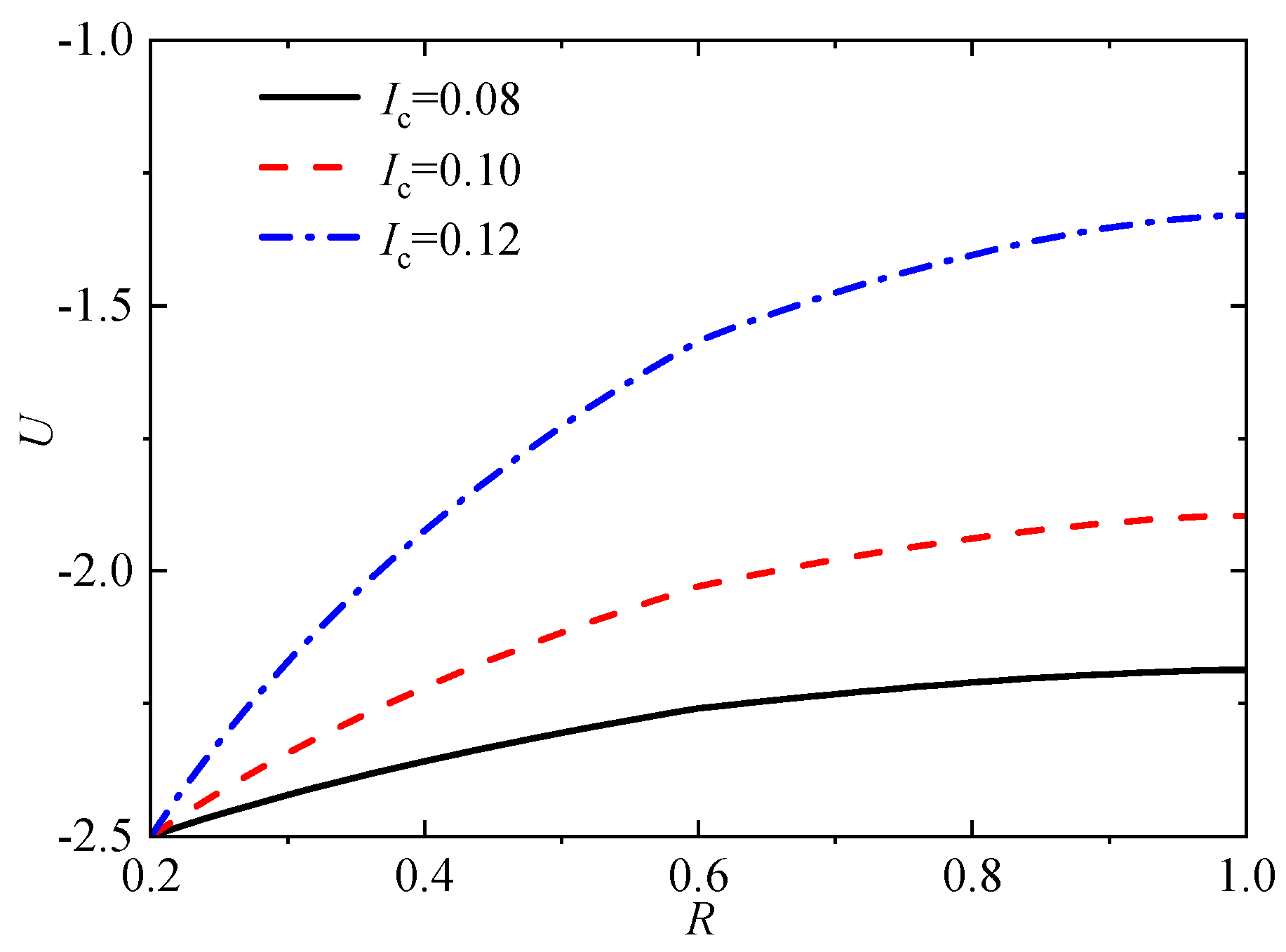
Figure 13.
Distribution of pore pressure with different permeability index α values (Tv=1).

Figure 14.
Distribution of pore pressure with different seepage parameter I0 values (Tv=1).

5.2. Analysis of Average Consolidation Degree and Settlement
Figure 15 shows the influence curve of three radial permeability coefficient variation modes on average consolidation and soil settlement. As seen, the permeability coefficient of the smear area shows a parabolic change, and the consolidation rate is the fastest (Mode 3). And Mode 1, where the permeability coefficient of the smear zone is constant and the consolidation rate is the slowest. In essence, when the permeability coefficients within the undisturbed zone are the same, the larger the average permeability coefficient of the smear zone is, the larger the whole consolidation rate of the sand-drained foundations will behave. For the sand-drained foundations' settlement, although the final settlement amount achieved by the three modes is consistent, ode 3 takes the shortest time to reach the same settlement amount under settlement proceeding, and Mode 1 takes the longest time. As a furtherly comparison, Mode 2 has a maximum relative deviation of 32.1% for the average consolidation degree and 18.9% for soil settlement compared to Mode1, and the maximum relative deviation of the two consolidation indexes in Mode 3 respectively reached 47.8% and 29.6% compared to Mode 1. That is to say, different radical permeability coefficient modes within the smear zone still have a significant impact on the consolidation rate of the sand-drained foundations, also indicating that the permeability modes should be reasonably adopted in practical engineering.
Figure 16 shows the influence curves of the top surface dimensionless vacuum negative pressure P0 on radial consolidation of sand-drained foundations under different loading modes. As seen, the maximum vacuum negative pressure has a relatively minor impact on the consolidation rate of sand-drained foundations under instantaneous loading. For sand-drained foundations under single-stage loading, the larger the top surface vacuum negative pressure is, the faster the consolidation rate will be. Moreover, with the increase of the dimensionless single-stage loading completion time Tv1, the influence of the top surface vacuum negative pressure on the consolidation rate becomes larger. Therefore, it can be concluded that for actual soft foundation treatment projects with longer loading duration, more attention should be paid to the impact of vacuum preloading on the consolidation rate.
Li and Qiu's [22] works have shown that the compression index (Ic) and permeability index (α) have the most concentrated range of variation, ranging from 0.08 to 0.12 and concentrated between 6 and 14 in order, so this section adopts Ic=6, 10, 14, and α= 0.08, 0.1, 0.12 for analysis. Figure 17 and Figure 18 show the influence of average consolidation degree and settlement with time factor under different compression index (Ic) and permeability index (α) values. As observed, the whole consolidation rate slows with the increase of the compression index or permeability index. As for the settlement amount, the compressive index has little influence on the settlement amount at the early consolidation stage. However, as time goes on, the larger the compression index, the more significant the settlement at the same time, and the final settlement also becomes more significant. Meanwhile, with the increase of the permeability index (α), the time to reach the same settlement amount decreases, but the final settlement amount is unaffected. Nevertheless, it also should be noted that, compared to α = 6, the maximum relative deviation of consolidation degree reached 54.9% at α = 10, and it reached as high as 76.6% when α =14. This indicates that although the permeability index α does not affect the final settlement, it has a significant impact on the whole consolidation process.
Figure 19 shows the average consolidation degree Up corresponding to different drain spacing ratio n, n = re/rw. As can be seen, the radial consolidation rate decreases with the increase of the drain spacing ratio. Especially, when n is greater than 40, the ratio has little influence on the consolidation rate. This also means that soil beyond a certain range will not be affected by the spacing ratio n, which reflects that the range of the influence zone is limited. Therefore, in practical engineering, for rapid drainage soft foundation consolidation with sand drains, the spacing of the drains should be reasonably arranged, such as n less than 40 is recommended.
Figure 20 shows the influence curve of the seepage parameter I0 on the average degree of consolidation Up and foundation settlement St at I0= 0, 1, 3, and 5, respectively. As seen, the consolidation and settlement rate with Darcy flow (I0 = 0) is faster than that of non-Newtonian index flow, and the whole consolidation and settlement rate becomes slower as I0 increases. For example, the corresponding Up values for increasing I0 are 58.61%, 69.33%, 79.74%, and 86.29%, respectively, and the maximum relative deviation has reached 38.2% when I0=5 compared with Darcy flow. Therefore, without considering the influence of non-Newtonian index flow, the consolidation and settlement rate of the sand-drained foundation will both be overestimated. Moreover, the settlement curves tend to be the same with time at different seepage parameter I0, indicating that the non-Newtonian index flow does not influence the final settlement.
Figure 21 shows the average consolidation and settlement curves under different negative pressure transfer coefficients k1. It can be found that the change of k1 has almost no effect on the whole consolidation degree of the sand-drained foundations. In contrast, the k1 undeniably impacts foundation settlement at the middle and late consolidation stages. As seen, the soil settlement rate and final settlement decrease with the decrease of k1, indicating that the long settlement deformation of actual engineering should also be paid more attention under vacuum preloading consolidation.
6. Conclusion
In this paper, an improved large strain consolidation system of soft foundations with sand drain is established considering the vacuum preloading, the double logarithmic compression permeability relationships, and the non-Darcy flow effect. The finite difference method is used to discretely solve it, and the validity of the numerical solution of the model is verified. Based on this, the consolidation behavior of sand drain improved soft foundations is deeply explored, and the following main conclusions are obtained:
Different variation modes of radical permeability coefficient significantly influence the consolidation rate of soft foundations with sand drain, among which the radical permeability coefficient of the smear zone keeps constant and has the slowest consolidation rate, and parabolic variation form has the fastest consolidation rate. Moreover, a linear variation of the radical permeability coefficient is in between.
The greater the maximum dimensionless vacuum negative pressure P0, the faster the consolidation rate of soft foundations with sand wells. Meanwhile, the more extended the loading duration, the greater the influence of vacuum negative pressure on the consolidation rate.
With the drain spacing ratio n increase, the consolidation rate of soft foundations with sand drains decreases. Especially, when the diameter ratio n > 40, increasing the healthy diameter ratio has little effect on the consolidation rate.
For the average consolidation degree Up (%), the consolidation rate of sand drain foundations decreases with the increase of compression index and permeability index. With the rise of seepage parameter I0, the consolidation rate of sand drain foundations will also decrease. Therefore, ignoring the non-Darcy flow effect will overestimate the consolidation rate of the sand well.
(5) With the increase of seepage parameter and permeability index, the time required to reach the same settlement decreases, but they do not affect the final settlement. In contrast, the settlement increases, and the final settlement increase with the increase of the compression index.
(6) The negative pressure transfer coefficient k1 has little effect on the consolidation rate of sand drain foundations, but a decrease in the negative pressure transfer coefficient k1 will result in a decrease in both the settlement rate and the final settlement amount of the sand drain foundations.
Author Contributions
Conceptualization; writing, Methodology, C.P.; Review and Editing, C.W.; Validation, Z.X. All authors have read and agreed to the published version of the manuscript.”.
Funding
This research was funded by the National Nature Science Foundation of China (grant 51879104), The support is gratefully acknowledged.
Data Availability Statement
The data that support the findings of this study are available from the corresponding author upon reasonable request.
Conflicts of Interest
The authors declare no conflict of interest.
References
- Basu, D.; Basu, P. , Prezzi, M. Analytical solutions for consolidation aided by vertical drains[J]. Geomechanics and Geoengineering. 2006, 1(1): 63-71.
- Walker, R.; Inraratna, B. Vertical Drain Consolidation with Parabolic Distribution of Permeability in Smear Zone[J]. Journal of Geotechnical and Geoenvironmental Engineering. 2006, 132(7): 937-941.
- Davis, E.H.; Raymond G., P. A non-Linear theory of consolidation[J]. Géotechnique. 1965, 15(2): 161-173.
- Xie, K.H.; Leo, C.J. Analytical solutions of one-dimensional large strain consolidation of saturated and homogeneous clays[J]. Computers and Geotechnics, 2004. 31(4): 301-314.
- Hansbo, S. Consolidation of clay with special reference to influence of vertical sand drains[J]. Swedish Geotechnical Institute Proceeding, 1960, 18: 45-50.
- Swartzendruber, D. Modification of Darcy’s law for the flow of water in soils[J]. Soil Science, 1962, 93(1): 22-29.
- Miller, R.J.; Low, P.E. Threshold gradient for water flow in clay systems[J]. Soil Science Society of America Journal, 1963, 27(6): 605-60.
- Mohamedelhassan, E.; Shang, J.Q. Vacuum and surcharge combined one-dimensional consolidation of clay soils. Can Geotech J, 2002. 39( 5) : 1126.
- Kianfar, K.; Indraratna, B.; Rujikiatkamjorn, C. , et al. Radial consolidation response upon the application and removal of vacuum and fill loading. Can Geotech J, 2015, 52( 12): 2156.
- Chai, J.C.; Hong, Z.S.; Shen, S.L. Vacuum-drain consolidation induced pressure distribution and ground deformation. Geotextiles and Geomembranes. 2010, 28(6): 525-535.
- Indraratna, B.; Rujikiatkamjorn, C.; Sathananthan, L. Radial consolidation of clay using compressibility indices and varying horizontal permeability[J]. Canadian Geotechnical Journal, 2005, 42 (5): 1330-1341.
- Geng, X.Y.; Indraratna, B.; Rujikiatkamjorn, C. Analytical Solutions for a Single Vertical Drain with Vacuum and Time-Dependent Surcharge Preloading in Membrane and Membraneless Systems[J]. International Journal of Geomechanics. 2012, 12(1): 27-42.
- Gibson, R.E.; England, G.L. , Hussey, M.J.L. The theory of one-dimensional consolidation of saturated clays. Part I: Finite nonlinear consolidation of thin homogeneous layers[J]. Geotechnique. 1967, 17 (3): 261-273.
- Fox, P.J.; Di Nicola, M.; Quigley, D.W. Piecewise-linear model for large strain radial consolidation[J]. Journal of Geotechnical and Geoenvironmental Engineering. 2003, 129 (10): 940~950.
- McVay, M.; Townsend, F.C.; and Bloomquist, D. One-dimensional Lagrangian consolidation. Journal of Geotechnical Engineering. 1989: 115(6): 893–898. [CrossRef]
- Perera, D.; Indraratna, B.; Leroueil, S. , et al. Analytical model for vacuum consolidation incorporating soil disturbance caused by mandrel-driven drains. Can Geotech J. 2017. 54(4): 547-560.
- Geng, X.Y.; Yu, H.S. A large-strain radial consolidation theory for soft clays improved by vertical drains[J]. Géotechnique. 2017, 67(11): 1020-1028.
- Nguyen, B.P.; Kim, Y.T. Radial consolidation of PVD-Installed normally consolidated soil with discharge capacity reduction using large-strain theory[J]. Geotextiles and Geomembranes. 2019, 47(2): 243-254.
- Walker, R.; Indraratna, B. Vertical drain consolidation with overlapping smear zones[J]. Géotechnique, 2007, 57(5): 463-467.
- Butterfield, R. A natural compression law for soils(an advance on e-log p'[J]. Geotechnique. 1979, 29(4): 469-480.
- Tavenas, F.; Leblond, P.; Jean, P. , et al. The permeability of natural soft clays, Part II: Permeability characteristics[J]. Canadian Geotechnical Journal. 1983, 20(4): 645-660.
- Li, C.X.; Qiu, C. An analytical solution for one-dimensional nonlinear large-strain consolidation of soft clay with high compressibility[J].Chinese Journal of Rock Mechanics and Engineering. 2021, 40(11): 2344-2356. (In Chinese). [CrossRef]
- Xu, Z.; Cao W.G.; Cui P.L; et al. Analysis of One-Dimensional Consolidation Considering Non-Darcian Flow Described by Non-Newtonian Index incorporating Impeded Drainage Boundaries[J]. Water. 2022, Vol.14(11): 1740.
- Cui, P.L.; Cao, W.G.; Xu, Z.; et al.One-dimensional nonlinear rheological consolidation analysis of soft ground under continuous drainage boundary conditions[J]. Computers and Geotechnics. 2023, Vol.156: 105283.
- Barron, R.A. Consolidation of fine-grained soils by drain wells[J]. Transactions of American Society of Civil Engineers. 1948, 74(6): 718-742.
- Xie, K.H.; Zeng, G.X. Analytical theory of sand well foundation consolidation under constant strain condition [J]. Chinese Journal of Geotechnical Engineering, 1989. 11(002): 3-17 (In Chinese).
- Li, G.X. . Advanced soil mechanics[M]. Tsinghua University Press. 2004:75-80 (In Chinese).
Figure 1.
Calculation diagram.

Figure 2.
Overload load modes.
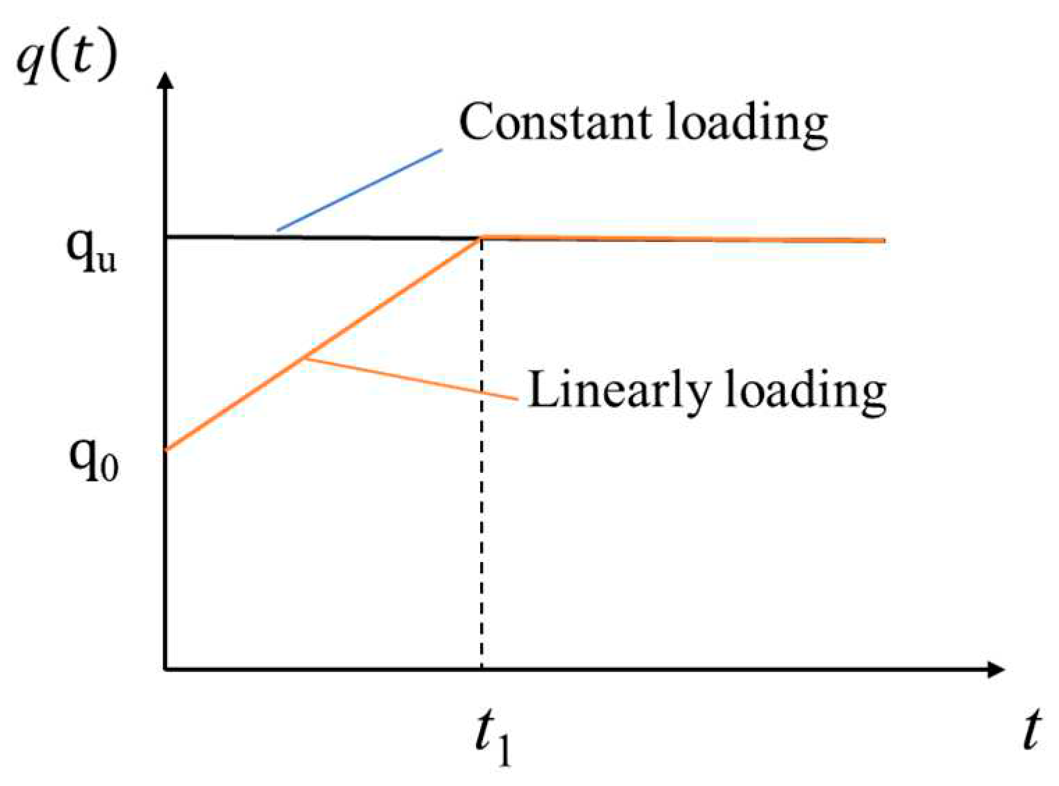
Figure 3.
The non-Newtonian index flow curve.

Figure 4.
Three variation modes of radial permeability coefficient in the smear area.

Figure 5.
lg(1+e)-lg σ′ compression curve.

Figure 6.
lg(1+e)-lg kr permeation curve.

Figure 7.
Theoretical vs. experimental comparison in this paper.

Figure 8.
Verification with the analytical solution.

Figure 9.
Distribution of pore pressure in the middle soil layer with different loading modes (P0=5, Tv=1).
Figure 9.
Distribution of pore pressure in the middle soil layer with different loading modes (P0=5, Tv=1).

Figure 10.
Distribution of pore pressure in intermediate soil layers with different loading modes (P0=20, Tv=1).
Figure 10.
Distribution of pore pressure in intermediate soil layers with different loading modes (P0=20, Tv=1).

Figure 15.
Up and St under three variation modes of radical permeability coefficient at smear zone.
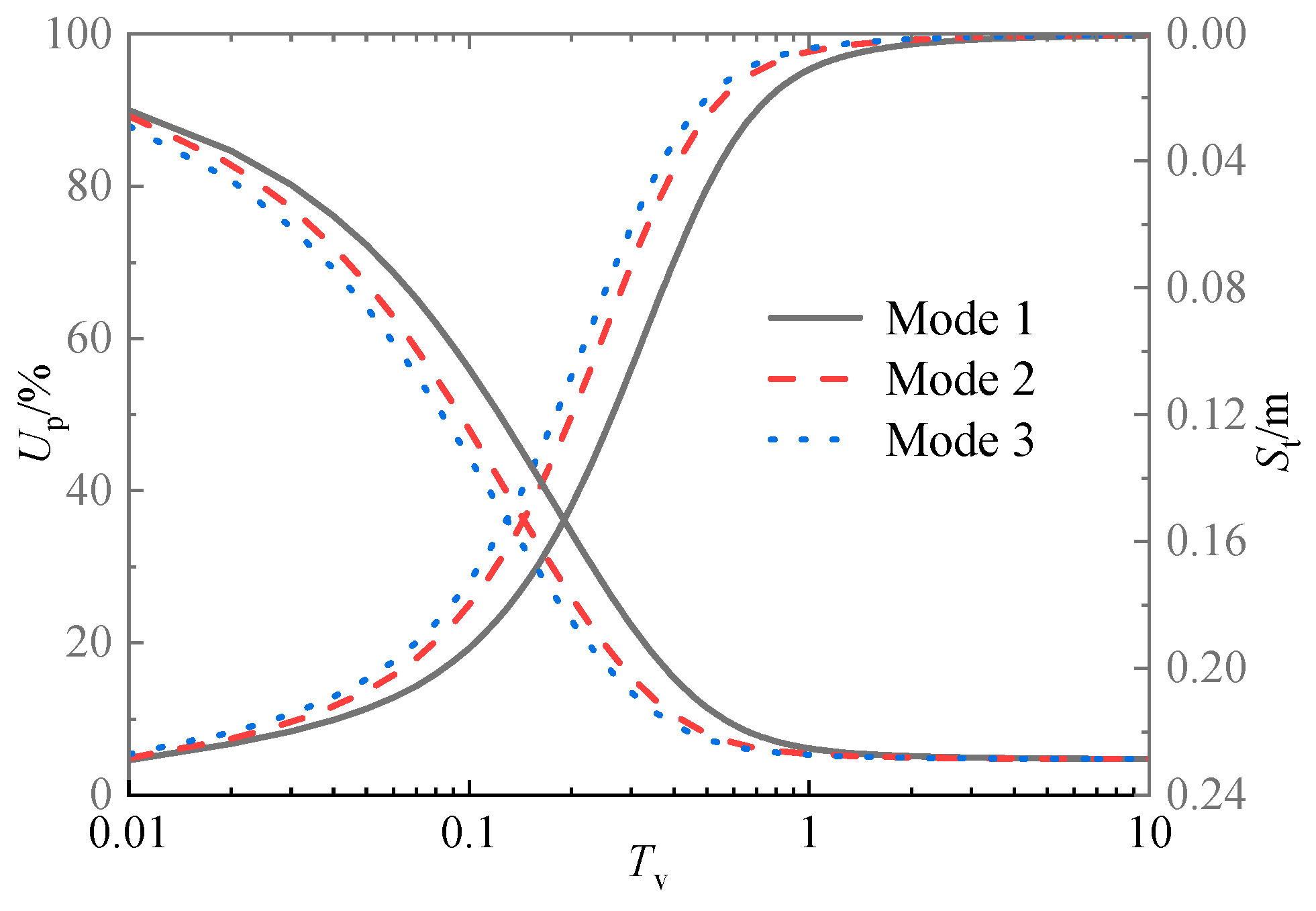
Figure 16.
Influence of vacuum preloading on Up under different loading modes.

Figure 17.
Up and St of different compression index Ic values.
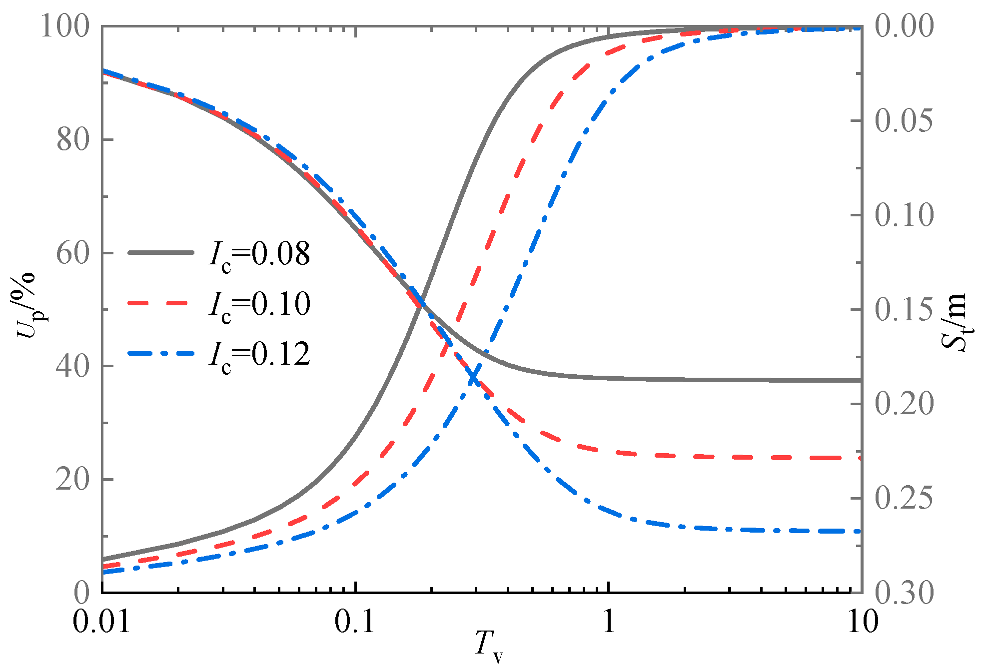
Figure 18.
Up and St of different permeability index α values.
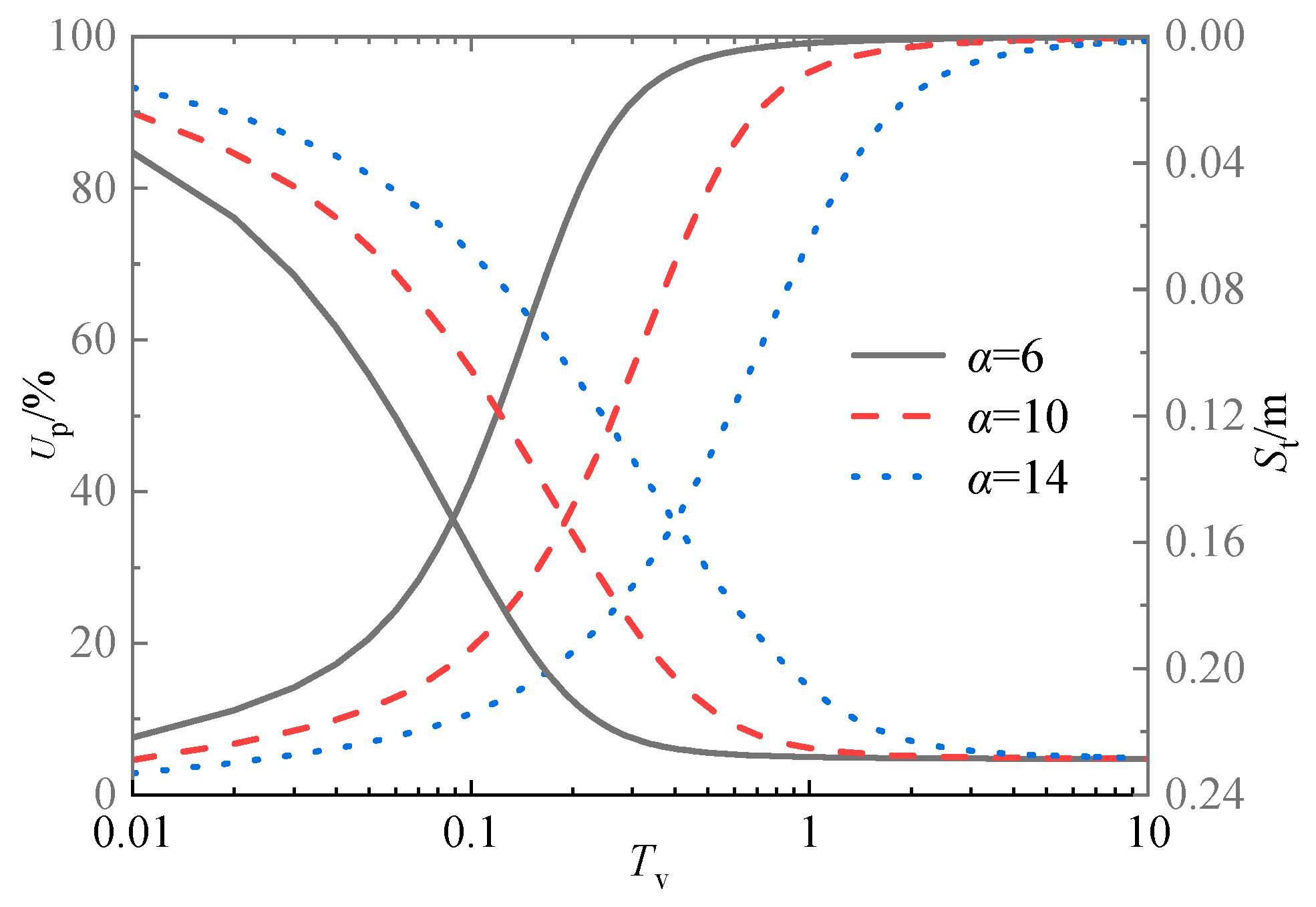
Figure 19.
UP curves with time Tv of different drain spacing ratio, n.

Figure 20.
Up and St under different dimensionless seepage parameter, I0.

Figure 21.
Up and St with time Tv curves under negative pressure transfer coefficient, k1.
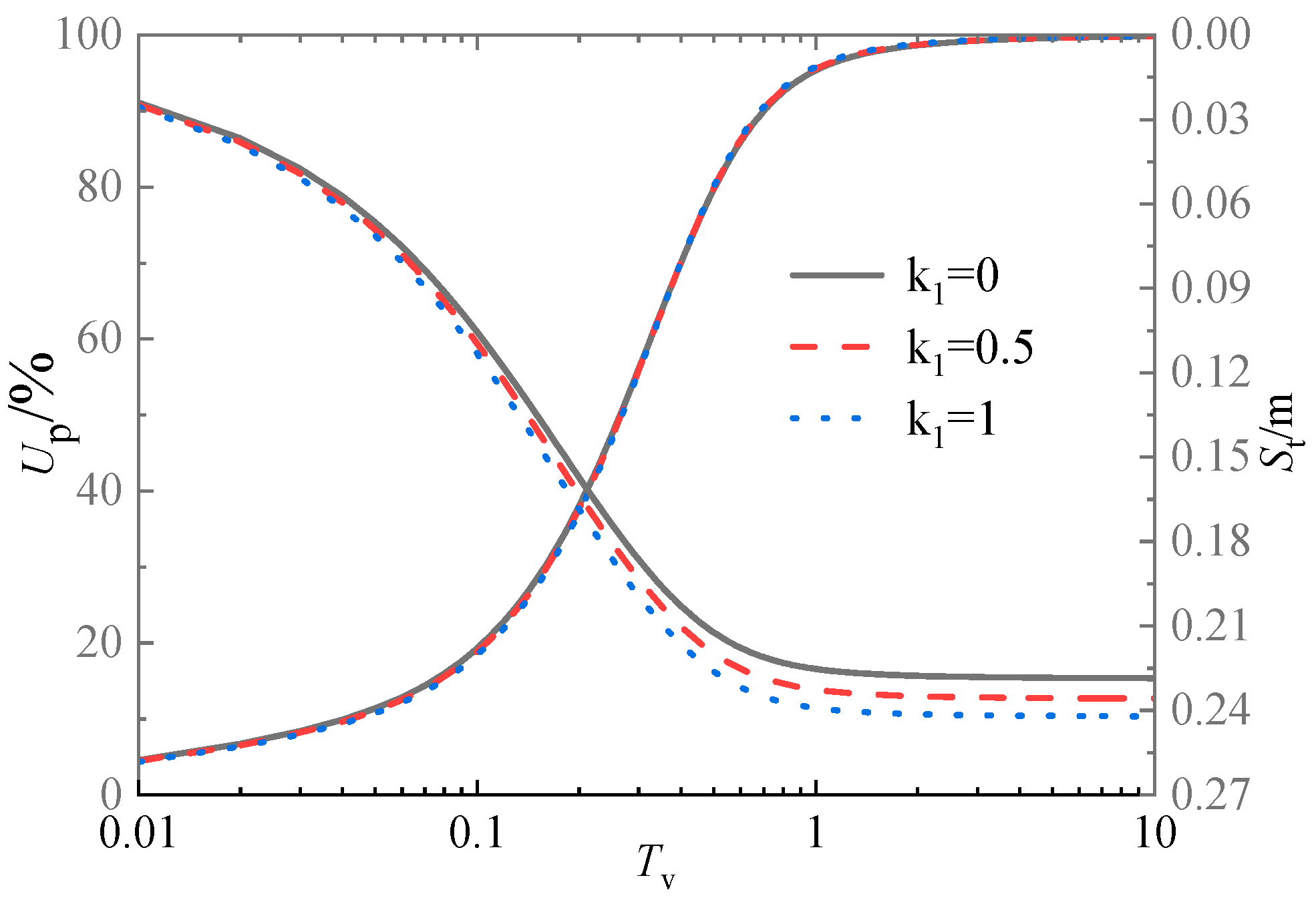
Table 1.
The geotechnical parameters from indoor tests.
| rw(m) | re(m) | rs(m) | kr0(m/s) | δ | σ0′(kPa) | e0 | qu(kPa) |
| 0.033 | 0.225 | 0.1 | 4.6×10⁻¹⁰ | 2/3 | 20 | 1 | 30 |
Disclaimer/Publisher’s Note: The statements, opinions and data contained in all publications are solely those of the individual author(s) and contributor(s) and not of MDPI and/or the editor(s). MDPI and/or the editor(s) disclaim responsibility for any injury to people or property resulting from any ideas, methods, instructions or products referred to in the content. |
© 2023 by the authors. Licensee MDPI, Basel, Switzerland. This article is an open access article distributed under the terms and conditions of the Creative Commons Attribution (CC BY) license (http://creativecommons.org/licenses/by/4.0/).
Copyright: This open access article is published under a Creative Commons CC BY 4.0 license, which permit the free download, distribution, and reuse, provided that the author and preprint are cited in any reuse.
MDPI Initiatives
Important Links
© 2024 MDPI (Basel, Switzerland) unless otherwise stated


