Digi-Max D1000 - Espar
Digi-Max D1000 - Espar
Digi-Max D1000 - Espar
Create successful ePaper yourself
Turn your PDF publications into a flip-book with our unique Google optimized e-Paper software.
<strong>Digi</strong>-<strong>Max</strong> <strong>D1000</strong><br />
Operating Instructions / Mounting Instructions<br />
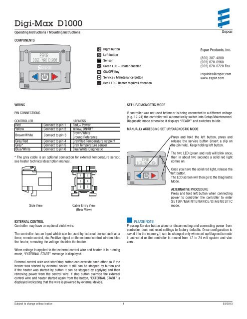
COMPONENTS<br />
WIRING<br />
PIN CONNECTIONS<br />
CONTROLLER HARNESS<br />
Red Connect to pin 1 Red,+ Power<br />
Yellow Connect to pin 2 Yellow, ON/OFF<br />
Brown/White Connect to pin 3<br />
Brown/White<br />
Ground Reference<br />
Grey/Red Connect to pin 4 Grey/Red Temperature setpoint<br />
Grey* Connect to pin 5 Grey Temperature sensor<br />
Blue/White Connect to pin 6 Blue/White Diagnostic<br />
* The grey cable is an optional connection for external temperature sensor,<br />
see heater technical description manual.<br />
Side View Cable Entry View<br />
(Rear View)<br />
EXTERNAL CONTROL<br />
Controller may have an optional violet wire.<br />
Right button<br />
Left button<br />
Sensor<br />
The controller has an input which can be used by external device such as a<br />
timer, remote control, etc. Positive signal on the external control wire enables<br />
the heater, removing the voltage disables the heater.<br />
When voltage is applied to the external control wire and heater is in running<br />
mode, “EXTERNAL START” message is displayed.<br />
External control wire and start/stop button can override each other so if the<br />
heater was started by external device it still can be stopped by button and<br />
if the heater was started by button it can be stopped by applying and then<br />
removing power from the control wire. If stop button override the external<br />
control wire and heater started again from the button, “EXTERNAL START” is<br />
displayed indicating that the wire is powered by external device.<br />
Green LED – Heater enabled<br />
ON/OFF Key<br />
Service / Maintenance button<br />
Red LED – Heater requires attention<br />
SET-UP/DIAGNOSTIC MODE<br />
If controller was not used before or is being connected to a different voltage<br />
(e.g. 12-24) the controller will automatically switch into Setup/Maintenance/<br />
Diagnostic mode otherwise it displays “READY” and switches to idle.<br />
MANUALLY ACCESSING SET UP/DIAGNOSTIC MODE<br />
<strong>Espar</strong> Products, Inc.<br />
(800) 387-4800<br />
(905) 670-0960<br />
(905) 670-0728 Fax<br />
[email protected]<br />
www.espar.com<br />
Press and hold the left button, press and<br />
release the service button (insert a clip on<br />
the pin hole). Keep holding left button.<br />
The two LED (green and red) will blink once,<br />
then in about two seconds a solid red light<br />
comes on.<br />
Once you have the solid red light, release the<br />
left button.<br />
The LCD screen will then go to the Diagnostic<br />
Mode.<br />
ALTERNATIVE PROCEDURE<br />
Press and hold left button when connecting<br />
power to controller the controller to enter<br />
SETUP/MAINTENANCE/DIAGNOSTIC<br />
mode.<br />
PLEASE NOTE!<br />
Pressing Service button alone or disconnecting and connecting power from<br />
controller, does not reset settings to factory defaults. Once configuration is<br />
saved into the memory, it can be changed only when set-up/diagnostic mode<br />
is activated or the controller is moved from 12 to 24 volt system and vice<br />
versa.<br />
Subject to change without notice 1<br />
03/2013
Operating Instructions / Mounting Instructions<br />
SET-UP/DIAGNOSTIC MODE continuation...<br />
SET-UP/DIAGNOSTIC MODE<br />
Controller checks the diagnostic line and displays “DIAG line OK” or “CHECK<br />
DIAG line!”. If diagnostic line is not OK, diagnostic feature is disabled.<br />
If diagnostic is option selected, fault codes are displayed for 10 seconds, then<br />
a prompt for erasing codes appears. If erase option is selected, fault codes<br />
will be erased and diagnostic menu appears again, so the codes may be read<br />
again or diagnostic skipped.<br />
Runtime counter value is saved in memory (power independent). If the value<br />
is not equal to zero, an option to reset the runtime is displayed, a confirmation<br />
message is displayed if you choose to clear the run time. If the left button (Y)<br />
is pressed, counter resets and “0:00” is displayed.<br />
Confirm runtime hours for maintenance period.<br />
Selecting one of the buttons (left, middle and right) will confirm the selection<br />
(e.g. right – 2000 hrs). Default value is 1000 hrs.<br />
<strong>Digi</strong>-<strong>Max</strong> measures system voltage and presets for 12 or 24 Volt systems. (if<br />
measured voltage exceeds 16 Volts, then 24 Volt system is assumed).<br />
Menu for selecting under voltage shutdown thresholds is displayed.<br />
Selecting one of the buttons (left, middle and right) will confirm the selection<br />
(e.g. right – 12.2). Default value is 12V.<br />
<strong>Max</strong>imum runtime value can be adjusted by pressing left button (decrease<br />
the value by 1) or the right button (increase the value by 1).<br />
Default value is 10 hrs. Values are from 1 to 24 hrs – less than 1 or above 24<br />
will change runtime into UNLIMITED (continuous).<br />
Controller displays “Fahren or Celsius?” message allowing choosing US or<br />
Metric options with left and right buttons respectively. If no selection is made,<br />
default will be Fahrenheit.<br />
Once the settings are done, the configurations are then saved in the DIGI-MAX<br />
<strong>D1000</strong> memory and the message “READY” is displayed for a brief period and<br />
the controller enters IDLE mode.<br />
Idle mode – controller ready for operation.<br />
If no selection is made, the default settings are applied.<br />
Subject to change without notice 2<br />
03/2013
IDLE/RUN MODE<br />
NO FAULT CONDITION<br />
IDLE MODE<br />
Middle button ENABLES the heater. GREEN LED light enabled.<br />
Green<br />
“ON”<br />
Temperature setpoint<br />
Runtime left until shutdown<br />
Left button pressed Right button pressed<br />
Pressing the Middle button again DISABLES the heater. GREEN LED<br />
light disabled.<br />
VOLTAGE TRESHOLD<br />
Green<br />
“ON”<br />
Green<br />
“OFF”<br />
In Running mode controller also monitors system voltage and stops heater if<br />
voltage goes below pre-programmed value and stays below for 10 minutes<br />
(factory default 12 Volt). After 8 minutes of undervoltage condition the RED<br />
LED comes on and a warning is displayed.<br />
After 10 minutes controller stops the heater and displays “LOW VOLTAGE<br />
STOP”message which remains on screen until next start.<br />
Green LED indication<br />
Red LED indication<br />
LCD screen information<br />
Enable/disable the heater<br />
When pressed, temperature set point goes up<br />
When pressed, temperature set point goes down<br />
WITH FAULT CONDITION<br />
Middle button ENABLES the heater. GREEN LED light enabled.<br />
Subject to change without notice 3<br />
03/2013<br />
Green<br />
“ON”<br />
When fault is detected GREEN<br />
LED turns off and RED LED enabled.<br />
The screen is alternately displayed<br />
until the Middle button is pressed.<br />
Actual and previous faults<br />
Red<br />
“ON”<br />
Short description<br />
of the actual fault<br />
Pressing the Middle button DISABLES the heater. RED LED light will<br />
then be disabled.<br />
Red<br />
“OFF”<br />
CHECK HEATER indication<br />
Green<br />
“OFF”<br />
Red<br />
“ON”<br />
PLEASE NOTE!<br />
Voltage shown in the controller is voltage detected in the internal circuits, not<br />
voltage from the source/battery voltage.
Operating Instructions / Mounting Instructions<br />
IDLE/RUN MODE Continuation...<br />
If an actual fault is detected, the controller starts switching between displaying<br />
regular information and fault codes. The heater is still enabled so if the issue<br />
is not critical and heater’s controller does not stop the heater, <strong>Digi</strong>-<strong>Max</strong> allows<br />
it to run.<br />
TEST MODE<br />
If all three buttons are depressed, at the time when controller first<br />
powered in rest, the controller proceeds into TEST mode, LEDs and<br />
backlight stays ON, text on screen displays:<br />
After all three buttons released, text is changed to:<br />
then backlight turns off after one second. Controller is halted and<br />
needs to be restarted by pressing “Maintenance” button.<br />
DRILLING TEMPLATE<br />
57.66 mm<br />
(2.27”)<br />
2 x Ø 7.5 mm (1/4”) FIXING S FOR<br />
ESPAR CONTROLLER LUGS<br />
20 mm<br />
(0.79”)<br />
Ø 9.5 mm (3/8”) FIXING<br />
FOR CABLE ENTRY HOLE<br />
If a fault code was previously detected in RUN mode, “CHECK HEATER”<br />
message appears in the following IDLE mode. Codes 53-56 (flame loss) may<br />
normally be overridden by automatic restart and are blocked from generating<br />
this message.<br />
If run time counter exceeds pre-programmed limit, “MAINTENANCE REQUIRED”<br />
message appears on the screen in IDLE mode.<br />
DEMO MODE<br />
Press and hold MIDDLE button when connecting power to controller forces<br />
controller to enter DEMO mode (USED FOR TRAINING PURPOSE ONLY – DEMO<br />
MODE will be displayed).<br />
In this mode set up menus have longer waits maintenance period is<br />
lowered to 5 min, etc.<br />
( 65.5 mm )<br />
(2.58”)<br />
( 44 mm )<br />
(1.73”)<br />
( 16 mm )<br />
(0.63”)<br />
SECTION A-A<br />
Subject to change without notice 4<br />
03/2013


